
This guide offers a detailed busbar pricing guide for electrical contractors, explores what affects pricing, and provides strategies to get the best value busbar products suppliers near you —without sacrificing quality. Buying busbars isn't just about getting the lowest. Our extensive online catalogue offers a wide selection of top-quality busbar solutions, as well as related products such as terminal blocks and current transformers, from leading brands such as ABB and Schneider Electric. Once you've selected your preferred products, simply proceed to checkout via. Your local electrical suppliers since 1936, we stock over 53,000 electrical supply products. Shop online, or at one of our New Zealand-wide stores today. View our range of products in Busbars, Terminals & Insulators. Buying busbars isn't just about getting the lowest price. Your decision. ACTI9 COMB BUSBAR 3P 100A 12MOD. Scott Electrical is your local electrical supplies store with an extensive range of products for sale in Auckland and across NZ. Designed and tested to excel in the most demanding environments. Browse, compare, and purchase with a streamlined shopping experience. Find everything you need to keep your systems running smoothly.
[PDF]

FTTH Networks: Wall-mount panels are used in apartment basements to distribute signals to individual units. Data Centers: High-density 4U panels are used for Top-of-Rack (ToR) switching. Broadcast & Media: Used for high-bandwidth 4K/8K video signal routing. This 2026 expert guide explains the functions, placement, structure, and application scenarios of ODFs and fiber patch panels-and includes a deep engineering FAQ that resolves real-world deployment challenges. Where Do ODF and Fiber Patch Panels Fit in a Modern Fiber Network? To understand the. Depending on different network construction scales and application environments, fiber optic cabinets and patch panels are typically used in various combinations. Choosing the right structural combination can significantly improve network construction efficiency. First is the standard. A Fiber Optic Patch Panel, also known as an Optical Distribution Frame (ODF) or fiber termination enclosure, is a centralized hardware unit designed to manage, protect, and organize fiber optic cable connections.
[PDF]

President Ibrahim Mohamed Solih highlighted on Friday the importance of connecting the country to the international fibre cable system, stating that it is a crucial step in establishing the Maldives as a hub for technology and innovation. The President's remarks at the inauguration of the Ocean. Today, we're announcing Dhivaru, a new Trans-Indian Ocean subsea cable system that will connect the Maldives, Christmas Island and Oman. This investment will build on the Australia Connect initiative, furthering the reach, reliability, and resilience of digital connectivity across the Indian Ocean. A new domestic Maldivan subsea cable from Dhiraagu and Ooredoo has landed on the island of Hulhumalé in the North Malé Atoll. Dubbed the Domestic Submarine Cable of Maldives (DSCoM), the telecommunications cable has five segments and will connect eight islands in the Maldives including Hulhumale'. Huawei Marine today announced that it has partnered with Ooredoo Maldives to deploy a Nation-wide Fiber Optic Submarine Cable, which will support the country's broadband policy and give the Maldives the most advanced ICT infrastructure in the SAARC region. The nationwide submarine cable utilizes.
[PDF]

A lighting control module operates as the central controller for a lighting system. It receives input from switches, apps, or sensors and regulates electrical flow to connected lights. Depending on the setup, it adjusts brightness, color temperature, or full lighting scenes. It acts as a bridge between your physical lighting fixtures and the smart systems that manage them. Instead of relying solely on traditional wall switches, you can control your lights via remotes, mobile or web apps. A lighting control module is an essential component in a lighting control system that manages how lights are powered, dimmed, or switched on and off. Think of it as the “brain” that receives commands—either from a manual switch, a sensor, or a building automation system—and translates them into. A lighting control module is a smart device that manages lighting circuits, adjusting brightness, automating schedules, and responding to sensors. It enhances comfort, efficiency, and ambience in homes and commercial spaces. Explore the multifaceted benefits and applications of lighting control modules, from home automation to industrial. These modules are designed to communicate with various sensors, switches, and control panels, making lighting adaptable to different environments and user preferences. It enables precise management of lighting systems, allowing for adjustments in brightness, color, timing, and even integration with other smart devices. This innovation.
[PDF]

Fiber optic cable pole brackets and hooks refer to the equipment used for mounting and securing fiber optic cables on utility poles or other vertical structures. (FOA) was founded in 1995 to help develop the workforce to build the fiber optic networks to support a rapid expansion in communications and the Internet. The charter of the FOA was to promote professionalism in fiber optics through education, certification, and. Indoor fiber optic cable uses tighter buffers and routes through conduits or trays. Outdoor fiber optic cable has rugged jackets, gel-filled or water-blocking layers, and armor to resist moisture, rodents, and temperature swings. You install indoor cables in controlled environments. Outdoor fiber. 4. FO-VC2 JOINT USE - VERICAL MIDSPAN CLEARANCES 48. FO-GB GROUNDING AND BONDING 49. FO-RI JOINT USE RISER. Our Fiber Optic Mounting Hardware category includes essential components designed to secure, organize, and protect fiber optic cables and equipment. Proper mounting hardware is crucial for efficient cable management, strain relief, and long-term network stability. However, installing fiber cables in outdoor environments exposes them to harsh weather conditions such as rain, thunderstorms, and freezing temperatures.
[PDF]

Precision begins with a quality optical encoder disc in the automation, robotics, and motion control systems of today. This tiny yet essential device transforms physical movement into exact digital signals that dictate speed, position, and direction. What constitutes an optical transceiver? An optical transceiver, a crucial device utilized in optical communication, is an optoelectronic element, allowing the interconversion of optical and electrical signals during the information transmission. It generally has the components for transmission. Therefore, NASA is developing optical communications to address limitations of radio frequency (RF) communications, including: bandwidth, spectrum and overall size of frequency packages and power used. Optical spectrum uses light as a means of transmitting information via lasers. Optical. Optical transceivers are devices that convert electrical signals into optical signals and vice versa, playing a key role in supporting modern high-speed communication networks. They are widely used in data centers and communication systems to enable high-speed, efficient transmission of large. Optical transceiver modules are designed and built by a variety of manufacturers. In the design of optical transceivers, the selection of channel configuration and modulation.
[PDF]

No, a 10G SFP (Small Form-factor Pluggable) module is designed to operate at 10 Gigabits per second (Gbps) and is not compatible with a 1 Gigabit per second (Gb) port. Therefore, a 10G SFP module will not work. When SFP optical module is inserted into the SFP port of Gigabit switch with fiber optic patch cable or copper cable, it can realize different distance transmission. For example, the maximum transmission distance is 160 km when using SFP1G-ZXC-55 optical module and LC duplex fiber patch cable, and. 10 Gigabit Ethernet (10GE, 10GbE, or 10 GigE) is a group of computer networking technologies for transmitting Ethernet frames at a rate of 10 gigabits per second. It was first defined by the IEEE 802. For example, when using the AE-SFP-ZX160 optical module and LC duplex fiber optic patch cords, the maximum transmission. Can 1G SFP optics work with 10Gb SFP+ ports on a 10Gb switch, or vice versa? This comprehensive guide reveals the intricacies of SFP and SFP+ compatibility and provides useful solutions for network switch users. Can 1G SFP Optics Run at 10G SFP+ Port? Can 10G SFP+ Optics Run at 1G SFP Port? Can. Small form-factor pluggable or SFP Modules can be described as compact and hot-pluggable hardware that connects various networking devices such as servers, routers, and switches. Networking standards, including Ethernet, Fiber Channel, and SONET, are also used with the SFP modules, broadening their.
[PDF]

Single-mode optical splitters are optimized for single-mode optical fiber, while multimode optical splitters are tailored for use with multimode optical fiber. An Optical Splitter, also known as a beam splitter, is a passive optical device that divides a single input optical signal into two or more output signals. Conversely, it can also combine multiple signals into one. Its primary role is in Passive Optical Networks (PON), which are the foundation of. This guide demystifies fiber optic splitters, explaining their design, operating principles, types, key specifications, and real-world applications. It can distribute the optical energy transmitted through a single fiber to two or more fibers in a predetermined ratio or combine the optical energy from multiple fibers into one fiber. “Passive” means it needs no. You use optical couplers and splitters to split or join signals in fiber networks. For example, optical splitters send light to many output ports. This lets you connect more users to one network terminal. There are different types of fiber optic splitters available, with two of the most common being Fused Biconical Tapered (FBT) splitters and Planar Lightwave.
[PDF]

OSFP, or Octal Small Form-factor Pluggable, is a high-speed transceiver form factor designed for next-generation data center networking. Compared with previous generations of optical modules, OSFP is optimized for higher bandwidth, better thermal performance and denser port. Among the various 400G optical transceiver form factors, OSFP stands out as a next-generation form factor specifically designed for high-speed Ethernet, offering clear advantages. This article introduces the fundamental concept and key characteristics of 400G OSFP Ethernet optical transceivers, and. Optech, a Taiwan-based optical transceiver manufacturer, provides professional 400G OSFP and 800G OSFP solutions designed for AI, cloud, high-performance computing, data center and advanced networking applications. Understanding MSA is critical for compatibility validation, cost. As data centers transition from 400G to 800G interconnects, bandwidth demand, power efficiency, and thermal constraints have forced the industry to look beyond traditional form factors. Designed to support 400 Gigabit Ethernet transmission with improved thermal performance and higher power capacity, OSFP modules are widely adopted.
[PDF]

DANGER Never look directly into an optical module or the ends of optical fibers. Optical modules and connected fibers emit laser radiation that can cause eye damage. NOTICE ● A switch must use optical or copper modules that have been certified for use on. Description: Huawei switches must use Huawei-certified optical modules. Non-Huawei-certified optical modules cannot ensure transmission reliability and may affect service stability. Huawei is not responsible for any problem caused by the use of non-Huawei-certified optical modules and will not fix. How to Configure Optical Ports on Huawei S5720-32P-EI-AC Switch? Problem: All optical ports cannot be connected, and the indicator lights are not on. Solution: To solve this problem, you can follow these steps: Check if the fiber and optical modules are compatible. Single-mode/multimode fibers and. Install an optical module on a port before connecting optical fibers to the transceiver module. Install dust plugs on idle optical ports. Wear an ESD wrist strap or ESD gloves. Before connecting the optical fiber to the. The method used to install a copper transceiver module is the same, except that the copper transceiver module connects to a network cable instead of optical fibers.
[PDF]
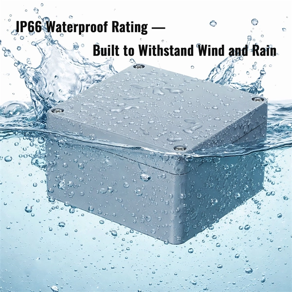
Look for boxes made from durable, weather-resistant materials. Plastic or fiberglass options often provide better waterproofing than metal ones. If you're unsure, consult with a professional or check product specifications to understand the waterproof ratings. Next, inspect the. A waterproof distribution box is an essential component used in various electrical installations to protect wiring and equipment from water damage. Typically constructed from durable, corrosion-resistant materials, these boxes are designed to withstand exposure to moisture and harsh environmental. What are the effects of chemicals on waterproof distribution boxes? The primary effects of chemical exposure on a waterproof electrical box include material degradation, stress cracking, and the loss of sealing integrity. Depending on the material (ABS, Polycarbonate, or Stainless Steel), contact. What is the difference between thermoset and thermoplastic materials? You can find distribution boxes made from various distribution box materials such as steel, aluminum, PVC, polycarbonate, high-density polyethylene, and thermoset plastics like SMC. These enclosures serve not only industrial applications but are also crucial for residential and commercial settings.
[PDF]

A mesh network wifi router (with satellites) is the best way to cover your home while overcoming signal degradation because of the walls and floors. Assuming your ISP is cable, wire a receptacle in a closet and pull the cable into the same closet. Plug in the main router there. A fiber-optic connection is the best choice for fast home internet as it has a number of advantages compared to traditional copper cables, such as faster speeds and less interference. Many major ISPs, such as Verizon and Xfinity, offer fiber connections directly to your door, known as FttP or Fiber. But if you want to get the full potential of this internet, invest in a Wi-Fi router that handles its speed and reliability. Put the satellite. Provides a nearly invisible fiber path to directly connect your modem to a computer, TV, or gaming console — no drywall repairs, no tripping hazards, no complaints from your spouse. Two Ethernet to fiber converters are included which allows connection to any devices with Ethernet ports. NEMA 1-15. However, you need a router capable of supporting multi-gig speeds to get fiber internet connectivity. With the many options available on the market, picking the best router for fiber internet can be tricky. Our top overall pick is the Netgear Nighthawk RS700S, a Wi-Fi 7 router built for multi-gig fiber plans that handles up to 200 devices across 3,500 square feet. For budget-conscious.
[PDF]
Over the past few decades, silicon-based solar cells have been used in the photovoltaic (PV) industry because of the abundance of silicon material and the mature fabrication process. Department of Energy (DOE) Solar Energy Technologies Office (SETO) supports crystalline silicon photovoltaic (PV) research and development efforts that lead to market-ready technologies. Below is a summary of how a silicon solar module is made, recent advances in cell design, and the. Silicon solar cells are the dominant technology in the global renewable energy transition, accounting for over 95% of the photovoltaic (PV) market share. Decades of engineering refinement have transformed this once expensive space technology into the most cost-effective source of new electricity. Photovoltaic (PV) installations have experienced significant growth in the past 20 years. During this period, the solar industry has witnessed technological advances, cost reductions, and increased awareness of renewable energy's benefits. Research activities at ISFH in the field of silicon. In the topic "Silicon Solar Cells and Modules", we support silicon photovoltaics along the entire value chain with the aim of bringing sustainable, efficient and cost-effective solar cells and modules to industrial maturity. However, as more electrical devices with wearable and portable functions are required, silicon-based PV solar cells.
[PDF]