Provides technical requirements concerning the construction, testing, and performance of metal cable tray systems. It is the first joint effort of NEMA and CSA International to put in one place standards for metal trays per both NEMA and CSA methods. Addresses shipping. association representing the major electrical equipment manufac-turers in the U. The Cable Tray ng standards, performance standards, test standards and application in this document have been tested extens ompetent professional en completely installed, without damage either to conductors or. Cable tray (or cable ladder) systems are a popular alternative to electrical conduit systems, as they have an outstanding record for dependable service, design flexibility and cost savings in commercial and industrial applications. A properly designed and installed cable tray system will provide. us-trations without notice. All illustrations, descriptions and technical information included in this document are provided as indications and can cable trays are equivalent. The mechanical and electrical characteristics, tests, certifications, overall quality management, recommendations mentioned. Not all cable trays are equivalent. The content is written to be SEO-friendly and compatible with Yoast SEO for WordPress. Introduction and.
[PDF]
Mouser offers inventory, pricing, & datasheets for IP67 Busbar Heavy Duty Power Connectors. Insulating busbar supports enable the fixing of copper or aluminum busbars and are tested to hold them safely during a short circuit. Profile for use with Adjustable Busbar Support (ABS) Insulator Modules. Adjustable Flat Busbar Support Kit enables to build custom adjustable flat busbar supports. Compact. Pricing (USD) Filter the results in the table by unit price based on your quantity. A tariff of 8% may be applied if shipping to the United States. A. If you are an organization seeking technical guidance on a large project, Vertiv can provide the support you require. Many customers work with a Vertiv reseller partner to buy Vertiv products for their IT applications. Partners have extensive training and experience, and are uniquely positioned to. Busbar supports with fixed interphase Busbar supports with adjustable interphase Insulators Function Characteristics SOCOMEC insulating busbar supports allow the fixation of a copper or aluminium bar or busbar. Insulators • Polyester without halogene. • UL94 VO self-extinguishable. • Colour red RAL. (1) Add Top Hat Rails, catalog number 141A-AHR45, page 23, to a module when a 141C-X40 (Adapter Extension Module) is being added to typically support the contactor on a 3 component starter. See also CrossBoard Universal Adapter Installation Instructions, publication 141C-IN004 for more information.
[PDF]

Recommendation ITU-T L. 163 describes criteria for the installation of optical fibre cables defined in Recommendation ITU-T L. 110 in remote areas with lack of usual infrastructure for installation including the procedures of cable-route planning, cable selection, cable-installation. The Fiber Optic Association, Inc. (FOA) was founded in 1995 to help develop the workforce to build the fiber optic networks to support a rapid expansion in communications and the Internet. They define a minimum baseline of quality and workmanshi for installing electrical products and systems. NEIS® are intended to be referenced in contrac documents for electrical construction ation or liability to users of this publication. Existence. This section covers Agency requirements for fiber optic service entrance cables intended for aerial installation either by attachment to a support strand or by an integrated self-supporting arrangement, for underground application by placement in a duct, or for buried installations by trenching. National Electrical Installation StandardsTM are designed to improve communication among speci-fiers, purchasers, and suppliers of electrical construc-tion services. This Standard may also apply to the Jet Propulsion Laboratory other contractors, grant recipients, or parties to agreements PR 8735. 2, Hardware Quality Assurance Program Requirements for Programs and Projects.
[PDF]

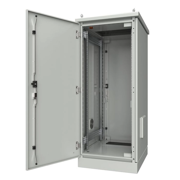
The purpose of the present invention is to provide an explosion-proof and flame-retardant distribution box, which has good explosion-proof and flame-retardant effect, strong impact resistance, is not easy to disperse, and has reliable safety performance. Flameproof enclosure (Ex d IIB+H2), which can be used as feed distribution equipment in control and distribution system (such as distribution box, switch box of main circuit, control box, terminal box or motor starting box etc. ) ·Enclosure: stainless steel. Equipped with specialized hinge. Substructure (use SSS=) and similarity (use ~) searches are limited to one per search at the top-level AND condition. Exact searches can be used multiple times throughout the search query. Searching by SMILES or InChi key requires no special syntax. To search by SMARTS, use SMARTS=. To search for. REV. Durable Hexlon Explosion Proof Distribution Boxes and Electrical Enclosures, IECEx and ATEX certified for Zone 1 and Zone 2. Design explosion-proof distribution box (control box) to meet equipment category and group requirements; b. They include fully modular low- and medium-voltage Ex-e, Ex-d, and Ex-p solution components, from Switchgear, Splitter Boxes, Junction Boxes, Ring Main Units, Power Supply, Motor.
[PDF]

Relay protection is the discipline of designing schemes that detect faults, coordinate relays, and isolate equipment without outages. It emphasizes selectivity, coordination, fault response, and system behavior rather than individual relay devices. Relay protection is often misunderstood as a. A protective relay is an intelligent electrical device designed to detect faults in power systems and initiate corrective actions such as tripping a circuit breaker. : 4 The first protective relays were electromagnetic. This document provides recommendations, background and philosophy on relay protection that is not available in M07. The facilities to which this Document applies are generally comprised of the fol-lowing: In analyzing the relaying practices to meet the broad objectives set forth, consideration must. What is a Protective Relay? A protective relay is an intelligent device that senses abnormal electrical conditions, such as overcurrent, under-voltage, or frequency deviations. It initiates the operation of circuit breakers to isolate the affected section. This prevents damage to equipment, reduces. Protective relays and devices have been developed over 100 years ago to provide “lastline”of defense for the electrical systems. They are intended to quickly identify a fault and isolate it so the balance of the system continue to run under normal conditions. The selection and applications of.
[PDF]
In, Structured cabling is the design and installation of a complete, standards-compliant telecommunications cabling infrastructure for,, or campus cabling. It is a systematic and organized approach that involves using a set of standardized, smaller elements (hence structured) called. To create a single, flexible, and scalable infrastructure that supports m.
[PDF]

This guide provides CISOs and IT leaders with an in-depth look at network security architectures. Perimeter security is the first line of defense, protecting the network from external threats. It includes firewalls, intrusion prevention systems (IPS), and other security devices that control network traffic at the network's boundary. When effectively designed, network security reduces threats like unauthorized access and malware from impacting your network or. Network security architecture is a strategy that provides formal processes to design robust and secure networks. Effective implementation improves data throughput, system reliability, and overall security for any organization. It explains the key concepts in plain language, dives into the core components, shares a framework for. Microsoft Defender for Cloud provides cloud security posture management (CSPM) and cloud workload protection (CWP). It assesses your resources for security compliance, provides a secure score to track your posture, and offers threat protection across Azure, on-premises, and multicloud workloads. It encompasses hardware, software, policies, and procedures.
[PDF]

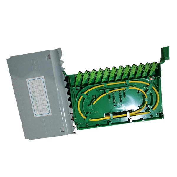
This complete guide explores everything you need to know about ODFs — from their structure, types, and key components, to installation best practices and modern design trends. Whether you're building a central office, data center, or FTTx distribution network, understanding the right ODF. An Optical Distribution Frame (ODF) is the central hub for fiber splicing, termination, patching, and cable protection in modern optical networks. This guide demystifies ODF, exploring their design, core functions, types, and how they. Fiber distribution hardware manages each fiber and connection point that is associated with active electronics. Why do operators, designers, and installers use additional fiber optic hardware racks for cable and fiber management? The active electronics are the most expensive part of the. A bad ODF can cause signal loss, slow repairs, and network outages. Let's talk about ODFs the way engineers and buyers need — with facts, clear advice, and practical steps. It's where. An ODF is a central hub in fiber optic networks, crucial for managing and organizing the variety of fiber-optic cables and connections entering a facility such as a telco central office (CO). Key points An optical distribution frame (ODF) is a central hub in fiber optic networks, crucial for.
[PDF]

Home and business fiber optics projects typically range from a few hundred to several thousand dollars, depending on run length, fiber type, and labor needs. The main cost drivers are materials, installation time, and environmental factors that affect trenching, conduit, and terminations. Commercial building installations with 100-200 network drops generally range from $15,000 to $30,000. Single-mode fiber costs less per foot than multimode fiber, but it requires more. What is Fiber optic network design? Fiber optic network design involves the planning, routing, and drafting of Fiber cable layouts to support high-speed data transmission. It includes detailed mapping of backbone, distribution, and drop connections for FTTH, FTTP, FTTx, and enterprise networks. Fiber optic network design refers to the specialized processes leading to a successful installation and operation of a fiber optic network. It includes first determining the type of communication system (s) which will be carried over the network, the geographic layout (premises, campus, outside. According to ResearchAndMarkets, the global market for fiber optics was estimated at $5. 8 billion in 2022 and is expected to reach $11. This is the dominant broadband access technology across half of OECD countries today. The price landscape varies from basic drop cables to enterprise backbone runs, with per foot and per reel pricing common in estimates. This guide presents cost ranges.
[PDF]
Interferometric fiber optic current sensors (FOCS) employ circularly polarized light traversing a closed loop path around an electrical conductor's current-generated magnetic flux, which reflects off a mirror. The light experiences a reciprocal phase shift as the refractive index, and effective path length, is modulated by the presence of a magnetic field, which optically induces circular. OverviewA current sensor (FOCS) is a device designed to measure. Utilizing a single-ended optical fiber wrapped around the current conductor, FOCS exploits the (. As FOCS are resistant to effects from magnetic or electrical field interferences, they are ideal for the measurement of electrical currents and high voltages in or other environme.
[PDF]

