Modern fiber-optic communication systems generally include optical transmitters that convert electrical signals into optical signals, optical fiber cables to carry the signal, optical amplifiers, and optical receivers to convert the signal back into an electrical signal. The information transmitted is typically digital information generated by computers or telephone systems. Transmitters The most commo. OverviewFiber-optic communication is a form of for from one place to another by sending pulses of or through an. The light is a form of. First developed in the 1970s, fiber-optics have revolutionized the industry and have played a major role in the advent of the. Because of its advantages over electrical transmission, optical fiber. is used by telecommunications companies to transmit telephone signals, Internet communication and cable television signals. It is also used in other industries, including medical, defense, governmen.
[PDF]
The electrical box is made of 0. 5 mm cold-rolled steel, featuring high toughness, pressure resistance, and rust resistance;The shell has an epoxy polyester powder coating with good mechanical and leveling properties Whether for outdoor installations or indoor electrical. The electrical box is made of 0. These enclosures not only organize complex wiring but also protect sensitive. NAHMA PLC is a premier metal enclosure manufacturer in Ethiopia, specializing in high-quality sheet metal fabrication. We produce durable, standards-compliant enclosures designed to protect sensitive electrical and electronic components in any environment. From standard junction boxes to large. Waterproof and weatherproof junction box for all electronic installation works. Check each product page for other buying options. Price and other details may vary based on product size and color. This junction box has high water resistance up to IP67, high dust resistance, and is suitable for outdoor street light connection, communication wiring, airport, construction, mechanical equipment, outdoor solar equipment and so on. It can. Junction boxes by cape electric are made from halogen free fibre reinforced Polycarbonate (Outdoor) / Polystyrene (Indoor) materials which are available in IP65 Range for Outdoor / Indoor Application. IP68 Ranges of Junction Boxes are used in Extreme application such as underwater or soil.
[PDF]
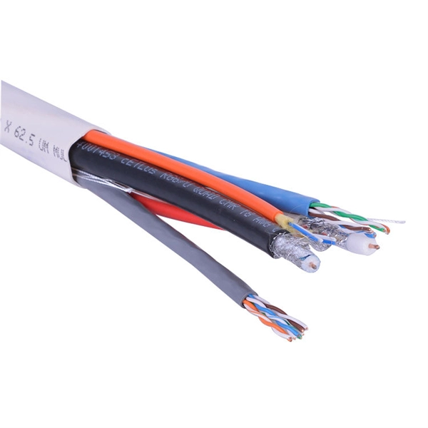
A single strand of glass fiber, called single-mode fiber, is used to transmit single-mode or light beams. It can transmit higher bandwidth than multimode fiber but requires a light source with a limited spectral range. In fiber-optic communication, a single-mode optical fiber, also known as fundamental- or mono-mode, is an optical fiber designed to carry only a single mode of light - the transverse mode. Modes are the possible solutions of the Helmholtz equation for waves, which is obtained by combining. A common type of optical fiber used to transmit over longer distances is single-mode fiber. One of two types of optical fiber, the other is multimode fiber. ” This technology is foundational to modern digital communication, enabling the high-speed transfer of massive amounts of data over vast distances. Generally, single mode cable has a narrow core diameter of 8 to 10µm (micrometers), which can propagate at the wavelength of 1310nm and 1550nm. Modes of light can only propagate through.
[PDF]
An OLT consists of three major parts: 1. Service port interface function - Provides translation between service interfaces and the TC frame interface of the PON section. 2. Cross-connect function - Provides a c.
[PDF]

Counted among the most trusted Cable Tray Exporters and Suppliers in Mauritania, we have all the electrical products available under one roof. Explore our excellent collection and place your order via call or enquiry directly from the website. Keep your cables safe and organized with our high-quality cable trays. Brilltech Engineers Pvt. Ltd is one of the trusted Cable Tray. Started back in 1983, Cable House is a recognized name engaged in manufacturing and supplying wide range including Hose Clamps, Cable Ties, Crimping Tools, Cable Tray, Industrial Connectors and more, to the national as well as the international market. With our manufacturing expertise, we have even. Looking to buy a MS Cable Tray in Mauritania? Jeetmull Jaichandlall (P) Ltd. We believe in building fruitful business partnerships. is a trusted brand that you can rely on. We have a well-equipped manufacturing unit with all the advanced resources to cater to your distinct requirements as per your industry preferences. Ltd would be pleased to introduce itself as one of the leading Electrical Panel Manufacturers in Mauritania. Our technology is up-to-the-mark and the technique we put in our process improves the quality and performance of our products and helps us. We offer Cable Tray in Mauritania in different specifications at competitive market prices.
[PDF]

The solution is to unplug the fiber and reinsert it into the SFP module interface until a “click” sound is heard, indicating the fiber connector and SFP module are properly connected. Contamination or damage on the fiber end face requires the use of a fiber end-face inspection. The physics of noise in optical communication links is of great interest in the design of fiber optic communication systems. The origins of noise in. Optical transceivers—such as SFP, QSFP, and OSFP transceivers —are essential components in high-speed data center and enterprise networks. These fiber optical transceivers convert electrical signals into light and back, enabling long-range, high-bandwidth communication over fiber optic links. Think of it. Optical transmission is vulnerable to various sources of signal degradation, including chromatic dispersion, modal dispersion, polarization mode dispersion, and noise. In the real world, an optical receiver's ability to resolve information is impacted by the presence of noise. They are the foundation of the network world. SFP optical modules are precision devices, and various faults may inevitably occur during operation. These faults can. Noise and Signal Interference in Optical Fiber Transmission Systems is a compendium on specific topics within optical fiber transmission and the optimization process of the system design. It offers comprehensive treatment of noise and intersymbol interference (ISI) components affecting optical.
[PDF]

A fiber is used to support G. 691 with a maximum rate of STM-16 or 10Gbit/s and a maximum transmission distance of 40 km (Ethernet) and STM-256 for G. This document outlines the specifications for a single-mode optical fiber and cable designed for use around the 1310 nm zero-dispersion wavelength, suitable for both the 1310 nm and 1550 nm regions, and compatible with analogue and digital transmission. It details the fiber's geometrical, optical. G. 652 is an international standard that describes the geometrical, mechanical, and transmission attributes of a single-mode optical fibre and cable, developed by the Standardization Sector of the International Telecommunication Union (ITU-T) that specifies the most popular type of single-mode. G. 652 optical fiber is a kind of optical fiber that is widely used in the network. 652 is mainly based on the requirements of PMD and the attenuation requirements at 1383nm. 652D is the type of optical fiber in the optical cable, which represents non-dispersion-shifted single-mode fiber, and is currently the most widely used single-mode fiber in China. This article will provide a detailed introduction to the structure, characteristics, and applications of standard single-mode fiber. G652 is a specification for optical fiber cables. It is part of the International Telecommunication Union (ITU-T) G.
[PDF]
Enter the dimensions of the cable tray, the desired fill ratio, and the diameter of the cables to calculate the cable tray capacity. This calculator helps determine the maximum number of cables that can be laid in a cable tray while adhering to the specified fill ratio. Follow these simple steps: Define Tray Dimensions: Enter the width and depth of your planned cable tray (in mm or inches). Select Fill Standard: Choose 40% for power cables (NEC compliant) or 50% for. A Cable Tray Capacity Calculator is an essential tool for electrical engineers, contractors, and project managers involved in the installation and management of electrical cables. Determine whether cables fit within safe fill limits. Accurate fill ratio analysis and tray sizing per NEC, IEC 60364, and BS 7671 standards. Enter your cable schedule below to get started. IEC 61537 covers cable tray and cable ladder systems for the support and accommodation of cables, while NEC Article 392 governs cable.
[PDF]

The Cable Tray Sizing Calculator is an electrical calculator tool designed to determine the correct cable tray dimensions for electrical installations. Accurate fill ratio analysis and tray sizing per NEC, IEC 60364, and BS 7671 standards. Follow these simple steps: Define Tray Dimensions: Enter the width and depth of your planned cable tray (in mm or inches). Select Fill Standard: Choose 40% for power cables (NEC compliant) or 50% for. The all-in-one desktop software for cable tray sizing, fill rate analysis, bracket design, seismic verification, and thermal expansion calculations. Fully compliant with IEC, BS, NEC, VDE, and AREI standards. cable tray engineering. From initial sizing to final documentation — one tool handles it. Calculate cable tray fill ratio, weight loading, and derating factors for multi-standard compliance. This calculator features an interactive interface with advanced visualizations. Open the full calculator for the best experience. 0133 sq in each, the screen is about 0. This page is a preliminary cable-tray occupancy screen for early layout work. You need to install 50 power cables, each with a diameter of 0. The calculator would help determine if the chosen tray is sufficient or if a larger size is. Determine the total usable cross-sectional area of the cable tray by multiplying its width by its height (or depth). For mixed cables, sum the areas of all individual cables.
[PDF]

THIS REPORT WAS PREPARED BY THE ORGANIZATION(S) NAMED BELOW AS AN ACCOUNT OF WORK SPONSORED OR COSPONSORED BY THE ELECTRIC POWER RESEARCH INSTITUTE, INC. NEITHER EPRI, ANY MEMBER OF EPRI, ANY COSPONSOR, THE ORGANIZATION(S) NAMED BELOW, NOR ANY PERSON ACTING ON BEHALF OF ANY OF. Vogtle Electric Generating Plant (VEGP) Units 3 and 4 Updated Final Safety Analysis Report, Revision 3, Section 3, Appendix 3F Cable Trays and Cable Tray Supports. This appendix provides the design criteria for seismic Category I cable trays and their supports. Seismic Category II cable trays and. The Pacific Earthquake Engineering Research (PEER) Centre has been developing a performance-based earthquake engineering (PBEE) methodology, which is based on explicit determination of performance, e. These rules have to be respected scrupulously by the engineering. Cable trays play a vital role in supporting electrical cables and wires in commercial, industrial, and utility installations. For proper installation, design, and maintenance, adherence to international standards is essential. One of the most recognized frameworks globally is the IEC standard for. CTI has committed most of its energies towards support services. The Cable Tray Institute is now making available our complete library of technical articles which have appeared in the Cablegram. For further assistance, contact David Richmond (NEMA Senior Program Manager) at David.
[PDF]
Complete guide to electrical box sizes and dimensions. Includes size charts, depth comparison, volume calculation and industrial metal electrical box selection tips. This guide helps you determine the correct dimensions based on wire fill capacity, device requirements, and installation environment, ensuring a safe and efficient electrical system. Selecting the appropriate junction box size prevents overcrowding, overheating, and potential hazards. Incorrect sizing can cause: Industrial and commercial applications especially require proper volume and internal space planning. Below are common. Understanding how to calculate the correct electrical box size is essential for ensuring safe installations that comply with electrical codes. These requirements apply to conductors 4 AWG and larger. Keep on reading to learn: How to use this electrical junction box.
[PDF]

To set up your router for fiber internet quickly, connect the router to your fiber modem, access the router's settings via a web browser, and input the provided ISP credentials. Make sure to update the firmware, configure Wi-Fi security, and customize your network name for. The first step in installing fiber optic cable is running the fiber line from the provider's network to your building. This can be done in two ways: Underground Installation – Fiber cables are placed in conduits underground, offering better protection from weather and physical damage. Since fiber. However, setting up a fiber optic connection to your router can seem daunting if you're unfamiliar with the process. In this guide, we'll walk you through how to connect a fiber optic cable to a router safely and efficiently. In this guide, we'll explain router compatibility, setup steps and whether upgrading your router is necessary to maximize fiber speeds. Make sure you've registered for your service. For quick download, open the camera on your smartphone and hold the camera over the QR code. After a few seconds, a notification will give you a link to open in your browser. Download the Smart Home Manager app from your app store or scan the QR code. The process involves a combination of national infrastructure, local engineering, and property-level setup. What Is Fiber Optic.
[PDF]

Whether you are a home user, managing a small office, or running a business network, this guide will walk you through connecting your ONT to your router, configuring your network, and optimizing your Wi-Fi for smooth performance. However, setting up a fiber optic connection to your router can seem daunting if you're unfamiliar with the process. In this guide, we'll walk you through how to connect a fiber optic cable to a router safely and efficiently. Why Use Fiber Optic Internet? Before diving into the setup, let's quickly. Setting up a fiber internet connection requires understanding key hardware components and following a specific connection sequence to establish your home network. The fiber. Fiber optic internet delivers lightning-fast speeds, reliable connections, and low latency for streaming, gaming, video calls, and more. Setting up your fiber router correctly ensures you get the most from your connection. This comprehensive guide combines industry standards with field-tested practices to ensure you achieve a rock-solid. In this guide, we'll explain router compatibility, setup steps and whether upgrading your router is necessary to maximize fiber speeds. Here's a simple guide to help you through the process: 1. Check Your Fiber Optic Equipment Before you start, make sure you have the necessary equipment: Fiber Optic Modem (ONT – Optical Network Terminal):.
[PDF]


