
We show the manufacturing process of DIMI's Fiber Optic Terminal Box / FTTH Termination Box—from raw materials and injection molding to assembly, quality inspection, and packaging. If you're looking for a stable supplier for OEM/ODM and bulk orders, this video helps you un. Our extraordinary customer service, flexibility and skill in managing complex operations in lower cost Southeast Asia has made us the. On June 4, FiberHome Communications' subsidiary Thailand Ruisen Co. (hereinafter referred to as "Ruisen") held a groundbreaking ceremony for its optical fiber and cable manufacturing base. Officials said that the base has a construction area of about 72,000 square meters. The first phase of. Fiber optic termination box is made of ABS and ABS+PC material, which is a box for protecting optical fiber cable and pigtail welding at the termination of the optical cable. As a professional fiber optical terminal box manufacturer, UnitekFiber provides fiber terminal boxes with various waterproof. With the global fiber optic market reaching $6 billion and growing at 10% annually, the need for high-quality manufacturing solutions has never been greater. Single-mode fiber represents the pinnacle of long-distance optical transmission technology. However, the very characteristics that make fiber optic cables.
[PDF]

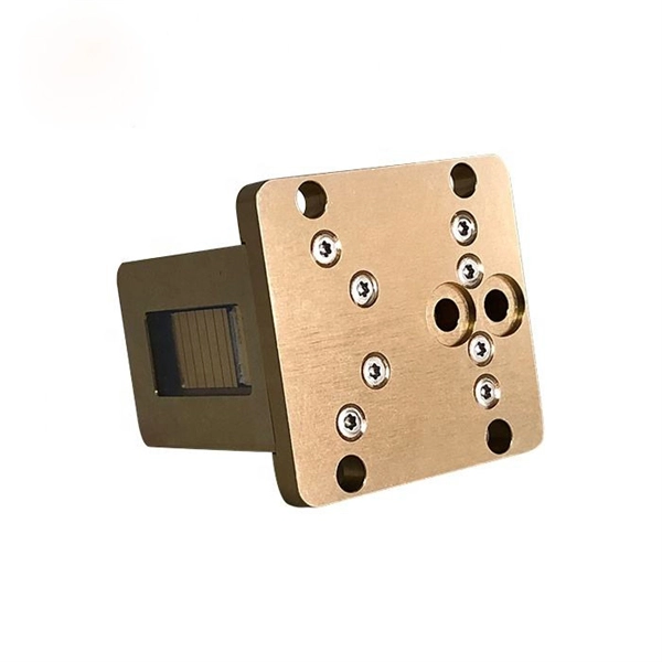
In all, there are five steps to manufacture a passive optical splitter. Each step requires strict control and management of various parameters like environment, temperature, and detailed precision on assembly and equipment. We will now provide a detailed introduction using PLC. A fiber optic splitter is a passive optical component that divides a single incoming optical signal into two or more outgoing signals, or combines multiple incoming signals into one. Unlike active devices (which require power), splitters operate without electricity, relying solely on the physics of. The Asia Pacific region (APAC) leads worldwide consumption of Planar Lightwave Circuit (PLC) splitter compact devices with a 68% share, followed by the Americas and the EMEA (Europe, Middle East, and Africa) region. The global PLC Fiber Optic Splitter market was valued at $4. 47 Billion USD in 2020. A fibre optic splitter like 1x2 Fiber Splitter is manufactured in five steps. Step 1: Component Preparation Generally, three components are required. The Evolution of Fiber Splitter Manufacturing Traditional fiber splitter production relied heavily on manual assembly and fused biconical taper (FBT) technology, which struggled to meet modern requirements for uniformity and miniaturization. It can divide the input optical signal into multiple output optical signals to meet the fiber optic access needs of multiple terminal devices.
[PDF]

This video shows key stages of manufacturing, from fiber preparation to final jacketing, ensuring consistent quality for FTTH deployments. Designed for aerial or duct installation. The FTTH cable production line is an integrated set of modules that converts fiber optic glass into finished drop and distribution products with repeatable quality. Compact Fiber Unit This overview helps factory managers, production engineers, purchasing teams, and learners in the. What's the FTTH Drop Cable? The FTTH drop cable is a type of fiber optic cable that is used to connect an optical network unit (ONU) to a user's premises. Structurally the FTTH Drop Cable consists of the following components. How to produce the FTTH Drop Cable? HK-50 IPC+PLC Control FTTH Drop Cable. A look at the production process of our 4-core flat drop cable. This video shows key. An overmolded connector or cable assembly is a finished electrical product in which a thermoplastic elastomer, typically TPE, TPU, or flexible PVC, is injection-molded directly over the connector body, cable jacket, or cable-to-connector junction to create a single, sealed, integrated component. Cable structure: bare fibers + steel wires/FRP strengthen members + LSZH/PVC/PE sheath, and other similar cables. 1, Precision special extruder and precision free adjustment head, the extruder is suitable for.
[PDF]

Outdoor Kitchen systems require structural durability, weather resistance, and long-term stability under changing environmental conditions. The manufacturing of outdoor kitchen cabinets involves a combination of material selection, precision fabrication, surface treatment, and quality control. Our manufacturing process blends traditional craftsmanship with advanced technology to create durable, stylish, and functional outdoor cabinetry. Partner with American Outdoor Cabinets as your expert outdoor kitchen manufacturer to deliver exceptional solutions tailored to your clients' need Our. hey have many advantages over wood. Wood for instance has to be finished, typically in mul�ple step processes, and in outdoor applica� ons typically fades, rots or warps. King StarBoard® ST and King StarBoard® WG are both environmentally stabilized and will not rust, delaminate, or ne re in a. Intelligent Manufacturing Ensures Precise Execution Once production begins, we treat every step as a critical part of quality assurance. Every technician follows detailed SOPs to ensure consistent results. This approach improves uniformity, strengthens traceability, and reduces human error. Dongguan shiru technology co. Was established in 2012. It is a company specializing in the production of outdoor projectors, three-proof intelligent constant-temperature cabinets, constant-temperature and constant-humidity cabinets, network cabinets, commercial display products, and sheet.
[PDF]

We are offering a comprehensive, fabrication-ready CAD file for a standard electrical distribution box. This isn't just a simple layout; it's a detailed mechanical drawing intended for electrical engineers, panel builders, and fabricators. High-performing, reliable product solutions that transmit data, power and signal in cars, planes, power grids, appliances, electro. Discover all CAD files of the "Power Distribution Boxes" category from Supplier-Certified Catalogs ✅ SOLIDWORKS, Inventor, Creo, CATIA, Solid Edge, autoCAD, Revit. The CAD files and renderings posted to this website are created, uploaded and managed by third-party community members. This content and associated text is in no way sponsored by or affiliated with any company, organization, or real-world good that it may purport to portray. It is running model of. Development of a distribution box for a meter. Download CAD block in DWG. 22 KB). Disassembly of a distribution box of a Perkins engine Already Subscribed? Free download Distribution box in DWG format or CAD block. This component, also known as a breaker panel or consumer unit, is the central nervous system for power management in any residential, commercial, or industrial setting. We design and manufacture a range of electrical products for the distribution, protection, control and management of electrical systems in low voltage environments. We help our customers to design and build their own.
[PDF]

In this guide, you will find a chronological description of the fusion splicing process, the principal technical standards, and answers to the real-life questions network engineers and procurement teams may have. TMM P021 OPTIC FIBRE CABLE JOINING, TERMINATION & MANAGEMENT Version 9. Therefore, we will also touch on cost factors, risk management, and best practices in. Fusion Splicing • Splicing is the process of connecting two bare fibres directly without any connectors. • Splicing provide much lower insertion loss compared to fiber connectors that's why Splicing is preferred over the use of Connectors. Fiber mechanical splicing – Insertion loss < 0. 5dB Fiber. What is Fiber Optic Splicing and Why is it Needed? – #1. Ensure Your Splicing Tools are Clean – #2. 56 was approved by ITU-T Study Group 6 (2001-2004) under the ITU-T Recommendation A. 8 procedure on 14 May 2003. The International Telecommunication Union (ITU) is the United Nations specialized agency in the field of telecommunications. By following the step-by-step guide provided, you can effectively perform fusion splicing to maintain high-quality fiber optic.
[PDF]

DFM in optical design refers to the process of designing optical components and systems that are manufacturable, testable, and inspectable. The importance of DFM lies in its ability to reduce production costs, improve product quality, and accelerate time-to-market. The SPIE Digital Library's coverage of design for manufacturability (DFM) predominantly centers on semiconductor and optical system manufacturing. The content heavily emphasizes photolithography-related DFM, detailing techniques for optimizing mask designs, optical proximity correction, and. Design for manufacturability (DFM) is a critical first step in the development of any optical component. In the context of optics, DFM involves optimizing the design of optical components and systems to minimize production costs, reduce. Optical assembly manufacturing combines precision components such as lenses, prisms, mirrors, and other components that must perform in demanding environments. Taking complex optical systems from simulation into production involves meeting a range of mechanical, functional, and other requirements. Today, we are expanding my very first blogpost from 2020 and discussing the concept of Design for Manufacturability (DFM). In this article, we explore why DFM matters and how key design aspects influence the success of plastic optics. Understand the Limitations of Injection Molding.
[PDF]
Interferometric fiber optic current sensors (FOCS) employ circularly polarized light traversing a closed loop path around an electrical conductor's current-generated magnetic flux, which reflects off a mirror. The light experiences a reciprocal phase shift as the refractive index, and effective path length, is modulated by the presence of a magnetic field, which optically induces circular. OverviewA current sensor (FOCS) is a device designed to measure. Utilizing a single-ended optical fiber wrapped around the current conductor, FOCS exploits the (. As FOCS are resistant to effects from magnetic or electrical field interferences, they are ideal for the measurement of electrical currents and high voltages in or other environme.
[PDF]
Hot-dip galvanized cable trays undergo a galvanization process where the steel tray is immersed in a bath of molten zinc. The process involves several steps, including surface preparation, zinc alloy formation, and cooling. In the case of outdoor or salty air, we apply the Hot-Dip Galvanizing. We immerse the tray that is done into a huge container of molten zinc at a temperature of approximately 450 C. This envelops every corner and edge in a thick protective layer. They feature convenient overall installation, a reasonable structure, a long service life, and an aesthetic appearance. Cables installed in fire-resistant cable. Here's why cable trays matter: Organization: They help organize cables neatly, preventing tangling or damage. Protection: They protect cables from being damaged by external factors like dirt, dust, and accidental impacts. Easy Maintenance: With cables clearly laid out and supported, repairs or. Fireproof galvanized spray-painted cable tray is a composite structure made entirely of steel. This advanced procedure ensures each tray is un. Ladder Type Cable Tray – Consists of two side rails connected with rungs spaced at regular intervals, designed for heavy-duty applications.
[PDF]

Optical attenuators use several principles in order to accomplish the desired power reduction. The types of attenuators generally used are fixed, stepwise variable, and. An optical attenuator is a passive device that is used to reduce the power level of an optical signal. The attenuator circuit will allow a known source of power to be reduced by a predetermined factor, which is usually expressed as decibels. Key requirements include minimal effect on the beam profile, low wavelength and polarization dependence, and sufficient power handling capability. The basic types of optical attenuators are fixed, step-wise variable, and continuously variable. Since too much light may saturate the fiber optic receiver, optical attenuators are often deployed in the system to reduce the light power and achieve the best fiber. An attenuator is a device designed to reduce the intensity of electrical and electromagnetic oscillations smoothly, stepwise, or at a fixed rate. It primarily ensures the power or amplitude of a signal is lowered without significantly distorting its waveform. Attenuators are extensively used across.
[PDF]

Home and business fiber optics projects typically range from a few hundred to several thousand dollars, depending on run length, fiber type, and labor needs. The main cost drivers are materials, installation time, and environmental factors that affect trenching, conduit, and terminations. Commercial building installations with 100-200 network drops generally range from $15,000 to $30,000. Single-mode fiber costs less per foot than multimode fiber, but it requires more. What is Fiber optic network design? Fiber optic network design involves the planning, routing, and drafting of Fiber cable layouts to support high-speed data transmission. It includes detailed mapping of backbone, distribution, and drop connections for FTTH, FTTP, FTTx, and enterprise networks. Fiber optic network design refers to the specialized processes leading to a successful installation and operation of a fiber optic network. It includes first determining the type of communication system (s) which will be carried over the network, the geographic layout (premises, campus, outside. According to ResearchAndMarkets, the global market for fiber optics was estimated at $5. 8 billion in 2022 and is expected to reach $11. This is the dominant broadband access technology across half of OECD countries today. The price landscape varies from basic drop cables to enterprise backbone runs, with per foot and per reel pricing common in estimates. This guide presents cost ranges.
[PDF]
Available in five IT load configurations from 18 to 90kW, this modular data center supports fast rollout, high reliability, and seamless integration—ideal for large-scale deployments and future-ready data center solutions. Delta InfraSuite is a new generation, highly integrated modular datacenter solution. It uses racks as the datacenter carrier and fully integrates all sub-systems including UPSs, cooling, power distribution, lightning protection, fire control (optional), wiring, airflow management, intelligent. The Delta Xubus Node is a prefabricated modular data center designed to meet this need—offering an offsite-built, plug-and-play solution that combines power distribution, cooling systems, and critical IT infrastructure into a factory-tested unit. As a global leader in thermal and power management solutions, Delta has further strengthened its leading position in data center infrastructure with a.
[PDF]

This complete guide explores everything you need to know about ODFs — from their structure, types, and key components, to installation best practices and modern design trends. Whether you're building a central office, data center, or FTTx distribution network, understanding the right ODF. An Optical Distribution Frame (ODF) is the central hub for fiber splicing, termination, patching, and cable protection in modern optical networks. This guide demystifies ODF, exploring their design, core functions, types, and how they. Fiber distribution hardware manages each fiber and connection point that is associated with active electronics. Why do operators, designers, and installers use additional fiber optic hardware racks for cable and fiber management? The active electronics are the most expensive part of the. A bad ODF can cause signal loss, slow repairs, and network outages. Let's talk about ODFs the way engineers and buyers need — with facts, clear advice, and practical steps. It's where. An ODF is a central hub in fiber optic networks, crucial for managing and organizing the variety of fiber-optic cables and connections entering a facility such as a telco central office (CO). Key points An optical distribution frame (ODF) is a central hub in fiber optic networks, crucial for.
[PDF]

