
They are designed to split unpolarized light at a specific Reflection/Transmission (R/T) ratio with unspecified polarization tendencies. A beam splitter or beamsplitter is an optical device that splits a beam of light into a transmitted and a reflected beam. It is a crucial part of many optical experimental and measurement systems, such as interferometers, also finding widespread application in fibre optic telecommunications. This division allows for the simultaneous analysis or utilization of the light's properties along two separate paths. The device is purely. Transmission and Reflection by. In addition to the task of dividing light, beamsplitters can be employed to recombine two separate light beams or. Explore the precision, applications, and design principles of beam splitters, essential for advancements in scientific research and technology. With WDS, a single X-ray energy – monochromatic X-rays – are counted at any given time. 19511; JEOL L-Value table2; CAMECA® SXFiveFE brochure3; Oxford Instruments Wave brochure4; Thermo ScientificTM NORANTM IbeX5). Unlike conventional beam splitters, PBSs ensure that the resulting beams are both linearly.
[PDF]

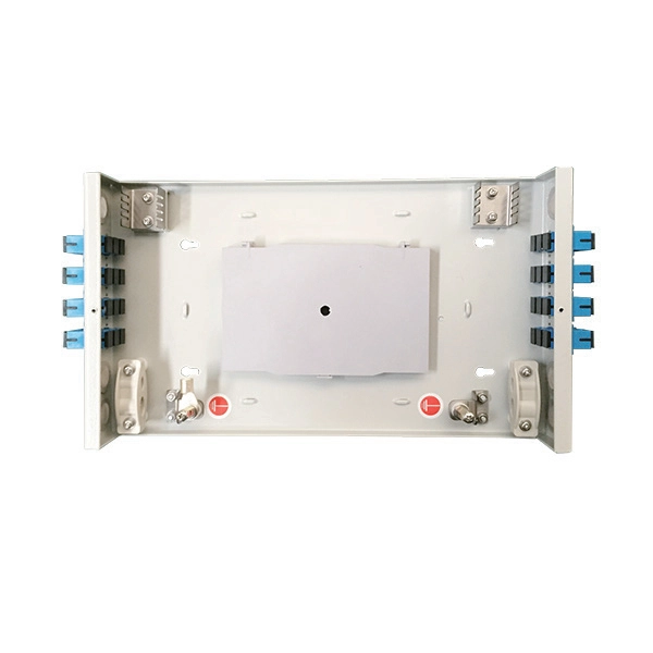
In all, there are five steps to manufacture a passive optical splitter. Each step requires strict control and management of various parameters like environment, temperature, and detailed precision on assembly and equipment. We will now provide a detailed introduction using PLC. A fiber optic splitter is a passive optical component that divides a single incoming optical signal into two or more outgoing signals, or combines multiple incoming signals into one. Unlike active devices (which require power), splitters operate without electricity, relying solely on the physics of. The Asia Pacific region (APAC) leads worldwide consumption of Planar Lightwave Circuit (PLC) splitter compact devices with a 68% share, followed by the Americas and the EMEA (Europe, Middle East, and Africa) region. The global PLC Fiber Optic Splitter market was valued at $4. 47 Billion USD in 2020. A fibre optic splitter like 1x2 Fiber Splitter is manufactured in five steps. Step 1: Component Preparation Generally, three components are required. The Evolution of Fiber Splitter Manufacturing Traditional fiber splitter production relied heavily on manual assembly and fused biconical taper (FBT) technology, which struggled to meet modern requirements for uniformity and miniaturization. It can divide the input optical signal into multiple output optical signals to meet the fiber optic access needs of multiple terminal devices.
[PDF]

This instrument enables high speed measurement of the optical properties of LD and LED light sources, optical amps, and other devices. To improve ease of use, it includes mouse-based user operation and a brand-new zoom function. If you want to resolve a technical support issue or need to contact YOKOGAWA, please fill out the inquiry form on our website. Thank you for purchasing the AQ6370D Optical Spectrum Analyzer. T o ensure correct use, please read this manual thoroughly before beginning operation. a question arises during operation. In addition to this manual, there is one individual manual each for the. The Yokogawa AQ6370D series optical spectrum analyzer is a high-performance and multifunctional testing instrument widely used in various fields such as optical communication, laser characteristic analysis, fiber amplifier testing, and WDM system analysis. This remote control user's manual covers the AQ6370C, AQ6370D, AQ6373, AQ6373B, AQ6375 and AQ6375B. YOKOGAWA provides registered users with a variety of information and services.
[PDF]
This paper presents a method for the CTE measurement of composite specimens using Fiber Bragg Grating (FBG) sensors. FBG sensors consist of periodic refractive index variation made on the core of optical fiber. When a broadband source is given to the FBG, one. Coefficient of Thermal Expansion is defined as where dl is the change in length for the temperature change dT and l is the original length. There are various conventional measurement techniques for the determination of the CTE, namely dilatometry , interferometry and thermomechanical. Measurement of the Coefficient of Thermal Expansion of Materials Access to the requested content is limited to institutions that have purchased or subscribe to SPIE eBooks. You are receiving this notice because your organization may not have SPIE eBooks access. Pure thermoplastic and composite specimens were built using different commercially available filament. A variation of the period of the grating inscripted in a fiber optic – induced by mechanical or thermal perturbation – causes a shift of the reflected peak wavelength, due to the related optical path length variation. where Pij are the Pockel coefficients of the elasto-optic tensor, n is the.
[PDF]
Commonly, a power meter on its own is used to measure absolute optical power, or used with a matched light source to measure loss. When combined with a light source, the instrument is called an Optical Loss Test Set, or OLTS, typically used to measure optical power and end-to-end optical loss.OverviewAn optical power meter (OPM) is a device used to measure the power in an signal. The term usually refers to a device for testing average power in systems. Other general purpose light power measuring. The major types are (Si), (Ge) and (InGaAs). Additionally, these may be used with attenuating elements for high optical power testing, or wavelengt. A typical OPM is linear from about 0 dBm (1 milli Watt) to about -50 dBm (10 nano Watt), although the display range may be larger. Above 0 dBm is considered "high power", and specially adapted units may measure u.
[PDF]

A relay protection tester is a core device used to verify the performance of relay protection devices. Its working principle can be summarized as “signal excitation – behavior detection. ”. It is divided into two parts: the main loop and the auxiliary loop. ” The tester has a built-in high-precision programmable power supply, capable of simulating various operating. When the transformer wiring type is Y/Y (Y0), the test wiring is very simple: when testing phase A, the tester IA is connected to the phase A of the high voltage side, and the tester IB is connected to the phase a of the low voltage side. After the neutral line of the high and low voltage sides is. Relay protection aids in detecting and preventing faults in electrical systems such as overcurrents or short circuits. As a core part of electric system reliability and safety, protective relays aid in preserving equipment and maintaining stability by isolating affected zones automatically via. THEY SHOULD BE GIVEN FIRST LINE MAINTENANCE ATTENTION. COMPREHENSIVE INSPECTION, MAINTENANCE AND TESTING PROGRAM. ” relay may only need to operate for 0. 15 seconds in its 30+ year life. But failure to operate as intended can result in extensive damage, extended power outages, and loss of life. NETA. Megger's smart relay testing solutions and expert support help you validate protection performance, improve system reliability, and ensure continuity of power across your network.
[PDF]
An optical power meter (OPM) is a device used to measure the power in an signal. The term usually refers to a device for testing average power in systems. Other general purpose light power measuring devices are usually called,, power meters (can be sensors or ), or lux meters. A typical optical power meter consists of a , measuring and display. The sens.
[PDF]

Call Boxes are to be located no higher than 48” front reach or 54” side reach to the center of the button above ground level. Call Boxes must include braille identifying the unit as an “Emergency Phone”. An elevator electrical wiring diagram is a visual representation of the electrical connections and components of an elevator system. This diagram is essential. An elevator is a complex mechanical and electrical system that requires careful construction and precise wiring to ensure safe and efficient operation. The wiring. The purpose of this T/C is to clarify wiring that is permitted to be located in an elevator hoistway, machine/control room, or control space/room. Call Commander(s) shall be connected to designated ports on the Distribution Module. cabling used shall be RATH® Cable RP7500094B or. In Oregon, Raceways and conduits for the connection of elevator devices shall only enter the machine room to the extent necessary to connect the devices attached thereto. 37 covers wiring in hoistways, machine rooms, control rooms, machinery spaces, and control spaces related to the. Eaton's Elevator Control panelboards provide electric power distribution with integrated fusible switches, metering, and surge protection. Additionally, they're designed to meet UL 67 and NEMA PB1 standards for use in data centers, industrial, commercial and healthcare facilities.
[PDF]

Find & hire the best Distribution Services in Morocco. Here are the best ones listed just for you based on verified client reviews. Casablanca and Tanger Med are the primary ports of entry for foreign manufactured goods for direct distribution. Ferry services between Morocco and Spain allow goods to be imported and exported by truck. The TangerMed port on Morocco's Mediterrean coast, which will have a throughput capacity of. Most trusted source for Tendering Opportunities and Business Intelligence since 2002 Get access to latest Morocco distribution boxes tenders and government contracts. Find business opportunities for Morocco distribution box tenders. Delivery And Installation Of Biomass Burners Together With. The FAIM label is your global assurance for a smooth, safe and comprehensive relocation process. Either: A signed original Change of Residence Certificate (in French), dated less than 6 months, and stamped on an official letterhead from the city hall or embassy at origin. The name and position of. In a very competitive and dynamic market, YAWGI Distribution has managed to position itself as a distributor of choice, more than 30,000 customers are part of our portfolio, spread across the geographical areas that we cover, mainly the South. Technological advances and the use of dematerialization are changing the paradigms of this business at all levels of the supply chain.
[PDF]

Primary distribution box: three-phase power supply, ground wire and zero wire are introduced from the transformer. Secondary distribution box: from the power line of primary distribution box to temporary power. It is specially designed for the special situation of the project construction site and meets the relevant construction power specifications and standards of the. A distribution box is installed under the main distribution box, and a switch box is installed under the distribution box. Electrical equipment is installed under the switch box, forming a three-level distribution. "Two level protection" mainly refers to the use of leakage protection measures. In. From the transformer's low-voltage side (0. From there, it is routed to individual building distribution boxes (secondary distribution boxes), which subsequently supply power to unit-level distribution boxes. In a newly constructed residential area, a 10kV power line is introduced into the substation. These boxes feature bottom entry and exit cables, front-opening doors, and main busbars connected with copper strips for optimal contact. They also include metering systems, ensuring.
[PDF]
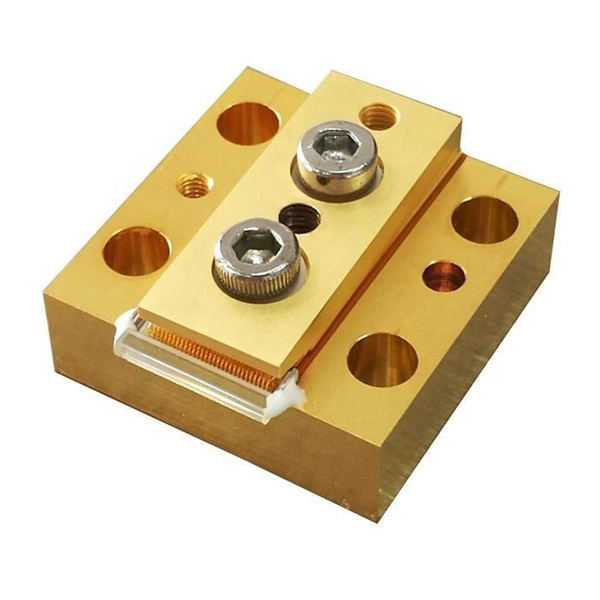
Laser diodes form a subset of the larger classification of semiconductor p – n junction diodes. Forward electrical bias across the laser diode causes the two species of charge carrier – holes and electrons – to be injected from opposite sides of the PIN junction into the depletion region.OverviewA laser diode (LD, also injection laser diode or ILD or semiconductor laser or diode laser) is a device similar to a in which a diode pumped directly with electrical current can create. A laser diode is electrically a. The active region of the laser diode is in the intrinsic (I) region, and the carriers (electrons and holes) are pumped into that region from the N and P regions respectivel.
[PDF]
Three level distribution: It is the control cabinet of the electrical equipment itself. The construction power distribution cabinet is specially designed for the special situation of the construction site. Comply with the construction department related construction. From the transformer's low-voltage side (0. 4kV), power is distributed to a main distribution panel (primary distribution box). From there, it is routed to individual building distribution boxes (secondary distribution boxes), which subsequently supply power to unit-level distribution boxes. Secondary power distribution;:From the primary distribution box power line to the temporary power supply, Three level distribution: It is the control cabinet of the electrical equipment itself. Electrical equipment is installed under the switch box, forming a three-level distribution. These boxes feature bottom entry and exit cables, front-opening doors, and main busbars connected with copper strips for optimal contact. They also include metering systems, ensuring.
[PDF]

These cables can be classified based on key parameters including fiber mode, fiber count, cable jacket rating, connector type, and end-face polish. There are different types of fiber optic cables because each type is optimized for specific applications that have unique requirements for bandwidth, transmission distance, and environmental factors. The choice of fiber optic cable depends on the specific needs of the application, as well as the. Fiber optic cables come in various types based on different specifications and application requirements. Unlike copper wires, which are limited by lower data transmission speeds, shorter transmission distances, and higher susceptibility to electromagnetic interference, fiber optic cables offer unparalleled performance and can. This quick guide will highlight the characteristics of OS2, OM1, OM2, OM3 multimode fiber, OM4, and OM5 fiber cables. The first difference to understand is the one that exists between OS and OM cables. The briefest explanation is that OS cables are all singlemode fiber, and OM cables are multimode. 801 is currently being finalized and should come into effect in mid 2010. It is eagerly awaited as it outlines the requirements for Category 6A components, but the amendment will also have significa c fibre optics used in industrial networks such as Interbus and Profibus. The second p nd AMD2.
[PDF]


