Learn how to install fiber splice trays inside an enclosure step by step. Quick, easy, and essential for fiber pigtail management! https://bit. Unlike fiber connectors, which can be plugged and unplugged, splicing creates a fixed connection that is typically more stable and has lower insertion. This document describes the installation of optical fiber with both single fiber and/or ribbon fiber splices into Optical Splice Enclosure (OSE) metal splice trays (Figure 1). Make sure you read and understand this instruction as well as instructions provided with related assemblies before. By following these detailed steps, the installation of your Fiber Splice Closure will be secure, organized, and maintained, ensuring high performance and longevity of your fiber optic network. Installing a fiber optic splice closure efficiently and effectively requires attention to detail and. How to install the splitter distribution box is the important information we need to know. This article includes the following: 1. Install the fixture 2. Box installation and fixed splitter distribution box 4. Install. Page 5 B (# 7 & 8) enter splice tray # 2. Route the fibers entering the splice tray up to splice point as shown. NOTE : Protection tube from side A enters splice tray from the far end as shown After splicing, close the splice tray and lock the front cover properly with the main and side lock.
[PDF]
Because fiber optic cables don't come in one continuous length, sections must be joined together through splicing. This process fuses two glass strands so light signals can travel through them without interruption. Below is a detailed look at each step of fiber optic network construction, including key terms and methods used across the industry. Engineers and. We are experts in the installation and use of fiber optic cable to residences, apartment buildings, businesses and cell sites. We complete complex construction projects consisting of aerial and underground deployments in varied, often difficult, working environments. Our services include everything. The Fiber Optic Association, Inc. (FOA) was founded in 1995 to help develop the workforce to build the fiber optic networks to support a rapid expansion in communications and the Internet. Delivers state-of-the-art fiber optics solutions by developing high-tech equipment and subcontractor expertise. Utilizes state-of-the-art technologies to splice a wide variety of different. This recommended practices document is a comprehensive manual for optical fiber construction and testing. Sections are included for project management; cable handling, testing and equipment; overhead cable placement; underground cable placement; underground enclosures; bonding and grounding; cable. 4. FO-VC2 JOINT USE - VERICAL MIDSPAN CLEARANCES 48. FO-GB GROUNDING AND BONDING 49.
[PDF]

The two primary industry-accepted methods for fiber optic cable splicing are fusion splicing and mechanical splicing. The choice between them depends on performance requirements, budget constraints, and the specific application environment. To begin, the standard definition of splicing in optical fiber is joining two fiber optic cables together. Splicing is most commonly used in the field but has application in cable assembly houses. Infield. In this guide, we cover the basics of fiber optic splicing, how to perform splicing using two different methods, and finally some best practices to perform good fiber splicing. What is Fiber Optic Splicing and Why is it Needed? – #1. In this guide, we'll explore what splicing of fiber entails, why it's important, and dive into the key methods and tools. So in essence, fiber optic splicing is a process used to join two separate fiber optic cables together. Through splicing, fiber optic technicians can extend the length of the fiber to make it long enough for use in a required cable run. As. Splicing fiber optic cable is an extremely important phase for making dependable, high-speed communication infrastructures. Termination is the other, more frequent way of linking fibers. Fiber splicing is the preferred way when cable lines are too long for a single length of fiber or when combining two different types of cable.
[PDF]

In this guide, you will find a chronological description of the fusion splicing process, the principal technical standards, and answers to the real-life questions network engineers and procurement teams may have. 📦 For purchasing, use the RP Photonics Buyer's Guide for fusion splicers. It provides an expert-curated supplier directory, buyer-focused technical background information, and structured selection criteria to support professional procurement decisions. This article explains the principle of fusion. Fusion splicers play a crucial role in the field of optical fibre communications by enabling the permanent bonding of two strands of glass fibre to create a continuous pathway for light to travel through. This process is achieved through precise alignment and fusion of the fibre ends using an. Fusion splicing is the process of fusing or welding two fibers together usually by an electric arc. Fusion splicing is the most widely used method of splicing as it provides for the lowest loss and least reflectance, as well as providing the strongest and most reliable joint between two fibers. Each splicer is equipped with a cleaver and stripper, conveniently includes in a single case. The goal is to align the microscopic glass cores (typically.
[PDF]

This guide covers everything: what fiber optic pigtails are, how they differ from patch cords, which connector and polish type to specify, how to choose between mechanical and fusion splicing, and the real-world applications where pigtails are the right call. In this guide, we cover the basics of fiber optic splicing, how to perform splicing using two different methods, and finally some best practices to perform good fiber splicing. What is Fiber Optic Splicing and Why is it Needed? – #1. Whether you're building out an ODF. Think of a fiber optic cable splice as the seamless stitching that keeps data flowing through the delicate threads of a network—like a master tailor joining fabric with precision. Whether repairing a broken cable or extending a fiber run, fiber optic splicing ensures light signals travel. Fibre optic splicing is an essential skill in the world of modern telecommunications, offering a reliable method to connect optical fibres for seamless data transmission. As the demand for high-speed internet and robust communication networks continues to grow, learning to splice fibre optics is. In this guide, you will find a chronological description of the fusion splicing process, the principal technical standards, and answers to the real-life questions network engineers and procurement teams may have. Therefore, we will also touch on cost factors, risk management, and best practices in.
[PDF]

BiDi SFP+ changes the geometry: each module uses a single fiber pair directionally separated by wavelength, so you can run one strand where you previously needed two. One of the most common decisions network engineers face is selecting between single fiber SFP and dual fiber SFP modules. This comprehensive guide explores the differences between single and dual fiber SFPs, their respective benefits, limitations, and use cases—helping you make an informed choice. A single fiber SFP, also known as a BiDi SFP, is designed precisely for this purpose—enabling bidirectional data transmission over a single strand of optical fiber. Unlike traditional SFP transceivers that require two fibers—one for transmitting and one for receiving—a single fiber SFP uses. SFP (Small Form-factor Pluggable) is a compact, hot-pluggable network interface module used to connect network devices (switches, routers, firewalls) to fiber optic or copper cables. An SFP interface on networking hardware is a modular slot for a media-specific transceiver, such as for a fiber-optic cable or a copper. Both transmitting and receiving need one optical fiber to connect. Simplex SFP modules, also known as BIDI transceiver, employs a unidirectional transmission mechanism and have only one port. In practice, that means fewer splice points, smaller patch panels, and less conduit congestion—especially in retrofit buildings.
[PDF]
Fiber testing is the process of verifying the performance of optical fiber cabling. This process includes a range of tests and measurements such as insertion loss, optical return loss, and fiber length. It encompass.
[PDF]
Fiber Internet Hardware: Quick Answer Fiber internet does not use a traditional cable modem. Instead, it requires an Optical Network Terminal (ONT) — a device supplied by your fiber provider that conve.
[PDF]
Optical Fiber Cable & Accessories Price in Nepal, Kathmandu. Buy with best and reasonable price @ ITShop Nepal. Nepal - Shop for Best Online at Daraz. np Wide Variety of fiber optic box. Great Prices, Even Better Service. Made of brand new materials, sturdy and durable, resistant to impact, corrosion, sealed and waterproof, safe and worry free Engineered for outdoor use, this junction box showcases a robust waterproof design, safeguarding critical fiber optic connections against harsh weather and ensuring reliable. Optical Fiber Cable & Accessories Price in Nepal, Kathmandu. SÜRGÜLÜ PATCHPANEL SC UPC DUBLEX 24XADAPTÖR 48XPIGTAIL RAL7035 1u 19” MEK. GJS-901-2 fiber optic splice closures (FOSC) are used to distribute, splice, and store the outdoor optical cables which enter and exit from the ends of the closure. There are two connection ways: direct connection and splitting connection. Applicable to situations such as overhead, man-well of. vianet: Vianet Communication Ltd. is a leading Internet & TV service provider in Nepal. Since 24 years, Vianet Communication has always remained at the forefront, providing reliable and affordable Fiber Broadband Internet Services.
[PDF]

Choosing the right fiber optic cable factory is vital to ensuring the performance, longevity, and reliability of your network. This article provides a guide from various dimensions on how to choose the right suppliers and manufacturers, along with a detailed. Selecting the right fiber optic cable manufacturer directly impacts your network's reliability, performance, and total cost of ownership. With the global fiber optic cable market valued at $13. 92 billion and growing at 10. The industry landscape features both global. This article highlights leading fiber optic cable manufacturers in the United States, renowned for their high-quality products and innovative solutions. For procurement managers and network engineers, the challenge is balancing performance, budget, and lead times. But if you want to find the best one, it's a bit difficult. Don't worry, Gcabling will help you. Gcabling, as a leading optical cable manufacturer that can. Based on 2025 rankings from industry sources like Owire and TSCables, the top manufacturers are evaluated on market share, innovation, and global reach. This list incorporates leading players, including Dekam-Fiber, Corning, Prysmian, and CommMesh, which stand out for their contributions to.
[PDF]
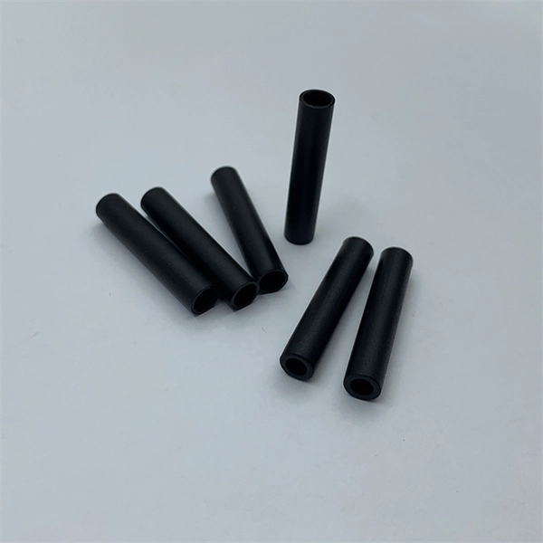
Yes. Standard scissors and a ruler will be adequate in most cases, unless you require an exact length of tubing, in which case use a more precise measuring tool. For thicker tubing you may require wire cutt.
[PDF]

Calculate end-to-end loss from cable length, connector and splice counts, and known component losses; verify with a light source + power meter (OLTS). If installed loss exceeds design, reduce connection points, rework poor splices, or use optics with better. This document presents a troubleshooting guide for fiber optic cables once deployed and in regular use. It also includes a list of common fault location items. How to troubleshoot: measure. Fiber optic networks are celebrated for their speed and reliability, but even the best systems can encounter problems. When issues like signal loss, slow speeds, or intermittent connectivity arise, systematic troubleshooting is key. These high-speed, high-capacity communication networks are increasingly replacing copper cables, offering superior performance and. Fiber optic troubleshooting is the systematic process of identifying, diagnosing, and resolving problems within fiber optic communication networks. These networks are the backbone of modern data transmission, offering incredible speeds and bandwidth. However, even the most robust systems can. Fiber optic cables are the backbone of today's high-speed communication networks, powering everything from FTTH broadband to data centers. However, like any technology, fiber optic systems can encounter issues that affect performance. Understanding the common causes and solutions helps maintain.
[PDF]

It is an interference type damper designed to attenuate the energy of cable vibration and restrain cable vibration amplitude by impacting with its damping section, so as to protect cables. Spiral vibration dampers have a helically-formed damping section sized for interplay of damper and cable to provide the action/reaction motion that opposed the natural vibration wave. The shock absorber damper is an interference type damper to attenuate vibration amplitude by impact with its damping section and especially designed for ADSS cable and OPGW cable of diameter less than. Spiral Vibration Dampers using its anti-vibration part to produce antihunt action to the wind vibration, consuming the vibration energy that produced by the cable running under the action of laminar wind,to prevent the destruction of gold tool and fiber optic cable, which mainly used for ADSS. Shop DigiKey's large in-stock selection of Spiral Wrap, Expandable Sleeving. View inventory, pricing and order now for same day shipping!.
[PDF]