This integration is achieved through the use of wavelength division multiplexing (WDM) filters, which separate the transmit and receive wavelengths within the same fiber. These modules play a vital role in transmitting and receiving optical signals. TOSA ( Transmitter Optical Sub-Assembly), converts electrical signals into optical signals for transmission. In this mode, the WDM system transmits multi-wavelength optical signals in receive and transmit directions through separate fibers. Simple design and low requirements. If you're dealing with data centers, telecommunications, or AI networking, grasping the key parameters of an optical. In the era of 5G, AI, and high-speed data centers, optical modules serve as the core bridge for converting electrical signals to optical signals (and vice versa), enabling fast, reliable data transmission across networks. Among various optical module form factors, SFP (Small Form-Factor Pluggable). Fiber optic transceivers are key components of the fiber optic transmission network. They are designed in small form-factor with some integrated optical sub-assemblies which can be suitable for the high-density network. There are many SFPs available in the market with different features and. Most systems operate by transmitting in one direction on one fiber and in the reverse direction on another fiber for full duplex operation.
[PDF]

Check 400G QSFP-DD price from the latest Cisco price list 2022. QSFP-DD transceiver module, coherent DCO generic, 400G-ZR. QSFP-DD 400G-ZR+ High TX Power DCO Pluggable - C-Band. QSFP-DD 400G-ZR+ High TX Power DCO - Licensed. There are several models available, including 400G-QSFP-DD-SR8, 400G-QSFP-DD-SR4, 400G-QSFP-DD-DR4, 400G-QSFP-DD-DR4+, and more, based on transmission distance, optical characteristics, and network environment requirements. You can select the most suitable model according to your specific needs. This plug-in module supports a data transfer rate of 400 Gbps, providing high-speed connectivity over long distances up to 3000 km. Designed for wired connectivity, it utilizes Digital Coherent Optics (DCO). AscentOptics' QDD-400S431-10CM 400G QSFP-DD PLR4 optical transceiver modules are designed to support 400G Ethernet, suitable for data center links up to 10km over single mode fiber with FEC. The 400G QSFP-DD PLR4 modules are compatible with IEEE 802. The transmission side converts. 400G QSFP-DD FR4 is a 400Gb/s Quad Small Form Factor Pluggable Double Density (QSFP-DD) optical module supporting link lengths up to 2km SMF through duplex LC connectors. It adopts 50G PAM4 and LWDM8 technology and supports 10km the maximum transmission distance.
[PDF]
These modules are designed to transmit 100G Ethernet signals across single-mode fiber over distances up to roughly 80 kilometers. The “BiDi” concept, short for bidirectional transmission, means that a single fiber strand carries traffic in both directions using different. The 80km SFP is a compact, hot-pluggable optical transceiver module standardized for long-distance fiber optical communication, with a maximum single-fiber transmission distance of 80 kilometers as its core performance indicator. It is designed to meet the interconnection needs of medium and. SFP (Small Form-factor Pluggable) modules have evolved beyond short-reach Ethernet, enabling reliable 80km and 120km links with optical performance, wavelength management, and power efficiency. This guide dives into the practicalities of 80km and 120km long-haul SFP modules, including key. It can reach up to 80km using single-mode fiber. This module is small and easy to swap. You can change it without turning off your network. The QSFP28-100G-ZR4 uses LAN-WDM technology. It sends many signals through one fiber. This makes your network. Cisco ® QSFP28 100G ZR extends 100GbE coherent links from QSFP28 ports reaching up to 80km over dark fiber and up to 300km over amplified Dense Wave Division Multiplexing (DWDM) links.
[PDF]

It transforms high volumes of electrical signals into optical signals for transmission over fiber cables, or reverses the process at the receiving end. Think of it like a Type-C to USB adapter in everyday tech—its core function is seamless conversion between electrical and optical. Optical modules are compact devices that convert electrical signals into optical signals and vice versa. They are used in fiber optic communication systems to transmit data over long distances with minimal loss and interference. These modules typically consist of a laser or LED transmitter, a. In the world of fiber optic communications, optical transceiver modules play a pivotal role as interfaces that convert electrical signals to optical signals and vice versa. An optical module works at the physical layer of the OSI model and is one of the core components in the fiber communication. The frequency response characterization of these electrical-to-optical (E/O, modulators sometimes integrated with lasers) and optical-to-electrical (O/E, photo detectors and receivers) converters can be important in terms of such parameters as bandwidth, flatness, phase linearity and group delay. The optical module serves as a crucial component in optical fiber communication systems, operating at the physical layer, which is the lowest layer in the OSI model. Among various optical module form factors, SFP (Small Form-Factor Pluggable).
[PDF]

An optical module sends data as light through fiber cables. Light is faster than electricity, making it great for quick communication. The optical module serves as a crucial component in optical fiber communication systems, operating at the physical layer, which is the lowest layer in the OSI model. Its primary function is to achieve optoelectronic conversion by converting electrical signals into optical signals and vice versa. This technology is crucial for fast and reliable data transfer in networks. Optical modules typically have an electrical interface on the side that connects to the inside of the system and an optical interface on the side that connects to the outside. Optical fiber transmission forms the backbone of modern high-speed communication networks, enabling the efficient transfer of massive datasets across vast distances. These modules typically consist of a transmitter, which converts electrical signals into a light signal, and a receiver, which converts the received signal back. In high-speed data networks, the seamless integration of fiber optic cables with SFP (Small Form-Factor Pluggable) modules is critical for reliable signal transmission. SFP transceivers bridge electrical and optical signals, making them indispensable in data centers, telecom networks, and.
[PDF]

Fiber-optic cables are made by taking an individual fiber or bundle of fibers and adding coating and protective layers. A TOSLINK optical fiber cable with a clear jacket. These cables are used mainly for digital audio connections between devices. A fiber-optic cable, also known as an optical-fiber cable, is an assembly similar to an electrical cable but containing one or more optical fibers that are used to carry. A fiber optic cable consists of five basic components: the core, the cladding, the coating, the strengthening fibers, and the cable jacket. When searching for a fiber optic cable, we need to pay attention not only to the connectors, such as SC to ST fiber cable, LC to SC fiber patch cable, or SC to. Data transfer and telecommunications have been transformed by optical fiber technology. It consists of tiny glass or plastic fibers that can carry data as light pulses. The first low-loss optical fiber was created in 1970 by Robert Maurer, Donald. At its simplest, a fiber optic cable is a hair-thin strand of incredibly pure glass designed to transmit information using light pulses instead of electrical signals. This fundamental difference is why it's so fast and efficient. The process relies on a principle called Total Internal Reflection. The optical fiber transmits the signal, the strength member provides tensile and crush resistance, and the jacket protects the overall cable from the environment. Govind Agrawal, the Dr. Wyant Professor of Optics at the.
[PDF]

For most setups, cables with 12, 24, or 48 cores are common choices, ensuring compatibility with modern equipment and ease of management. Fiber cores are the heart of fiber optic cables, transmitting light signals that carry data. Made from either high-quality glass or plastic, the core plays a critical role in determining the cable's performance. The total number of cores for a 1pc fiber patch cable is calculated as the number of. In fiber optic cables, data is transmitted as pulses of light that travel along a thin strand of glass or plastic fiber. The light is typically. The number of optical cores in an optical fiber is the total number of equipment interfaces multiplied by 2, plus 10% to 20% of the spare quantity, and if the communication mode of the equipment has serial communication and equipment multiplexing, you can reduce the number of cores. The following ZR Cable introduces some methods to determine the number of fiber cores. First of all, clearly know the number of wiring points in this layer, calculate the number of switches, and whether the connections. A fiber-optic cable, also known as an optical-fiber cable, is an assembly similar to an electrical cable but containing one or more optical fibers that are used to carry light. ” However, when light enters the core it needs to remain within it, and one layer that ensures that is called.
[PDF]

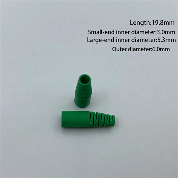
Align the fiber with the connector's guide. Ensure the fiber does not bend or twist during insertion. A proper fit prevents signal loss and enhances performance. Secure the connection using the fast connector's. Optical fiber fast connectors, also known as cold connectors, are becoming increasingly popular due to their ease of use and quick installation. Unlike traditional fiber connectors that require epoxy and polishing, fast connectors use a mechanical splice to join the fibers. In this article, we will. At the heart of any robust fiber optic network lies a crucial process: Preparing a fiber cable for termination of a connector or splice. Two types of splices are used in fiber optic cabling one is Mechanical the other is Fusion. Whether you're installing a new network, expanding an existing one, or. Optic Fiber cleaving, and mechanical splicing through very simple processes in this short series of videos. Thank you for supporting us by viewing our content. Doubts and suggestions? Leave us you. more Audio tracks for some languages were automatically generated. The primary purpose of a fast connector is to ensure a stable and reliable link. Connecting a fiber optic cable to a connector is a precise task that requires careful attention to detail, as well as some specialized tools and equipment. These terminations must be of the right style, installed in a.
[PDF]

These cables consist of delicate glass tubes layered with polymeric materials. Improper handling can lead to flawed connections and harm to optical components. Protective gear like safety glasses with side shields and gloves should always be worn when working with fiber. Fiber optic cable and copper twisted-pair cable share many similarities. They are both delivered in a coil or on a reel. They are installed in the same general location by the same people for the same general purpose. It is imperative that certain procedures be followed in the handling of these cables to avoid damage and/or limiting their usefulness. A copper wire can take a twist with little worry, but glass. Proper maintenance of fiber optic cables ensures years of reliable performance. Here are some tips you can follow when handling and storing fiber optic cables 1. Keep Cable Connectors Clean and Dry Before using fiber optic cables, clean the connectors on the cable and on the cables or ports the. Safely managing fiber optic cables is crucial to maintain their efficiency and prevent potential damage, despite their considerable tensile strength compared to copper. Here's a detailed breakdown of how to safely manage them: Glass fibers are extremely small and sharp; they can easily penetrate the skin, eyes.
[PDF]

When it comes to testing fiber optic cables, a Visual Fault Locator (VFL) is an essential tool in your toolkit. A VFL is used to detect faults, breaks, or bends in fiber optic cables by emitting a bright red light that is visible even through the fiber's jacket. Let's dive into everything you need to know about mastering VFLs. It's a cost-effective and. Visual Fault Locator (VFL) testing is one of the most fundamental inspection methods used in FTTH, ODN, and data center environments. A VFL emits a visible red laser (typically 650 nm) that travels along the fiber core and leaks out at points of excessive loss, fiber breaks, or microbends. Although. The Fiber Visual Fault Locator Kit is an essential tool for network technicians and engineers; it provides an accurate and quick method of finding such problems as breaks, bends or faults that may affect the network's operation. It works by injecting a visible red laser light (usually in the 650nm wavelength) into the fiber. When the light encounters a fault, such as a break, bend, or bad splice, it leaks out of the fiber, making the. Conducting efficient, repeatable fiber optic cable certification requires an array of specialized test equipment: Optical Loss Test Set (OLTS) – Integrates adjustable light source and power meter for efficient, Tier-1 insertion loss testing. Visual Fault Locators – Handheld devices projecting.
[PDF]

This article explains the modulation formats used in coherent optical systems (QPSK, 8/16/64-QAM), how DSP and OSNR tradeoffs determine reach vs. capacity, why probabilistic constellation shaping (PCS) matters, and how pluggable coherent modules (QSFP-DD / ZR / ZR+). A coherent optical module (Coherent Optical Module) is an advanced optical transceiver that utilizes coherent optical communication technology to encode and transmit data by manipulating multi-dimensional information such as the amplitude, phase, and polarization of light. Unlike traditional. Co-packaged optics (CPO) has emerged as an ultimate solution for achieving the ultra-high bandwidths, shoreline densities, and energy efficiencies required by future GPUs and network switches for AI. Among these challenges, power efficiency. ong-haul coherent optical communications systems. Due to limitations in space, it focuses mainly on coherent optical systems usin major milestone in long-haul transmission [1, 2]. Coherent receivers were intensively studied in the eighties [3–7] because of their superiority to their. =============================================================================== QSFP-DD Connector =============================================================================== Description : -Interface : 8/1/c7 FP Number : 2. Diag Capable : yes Number of Lanes : 1 Connector Code : LC.
[PDF]
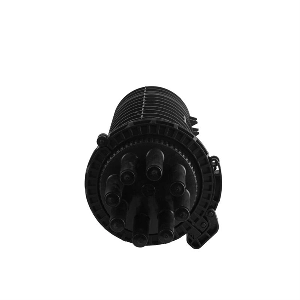
In summary, hermetic packaging uses metal and glass to provide tight protection for fragile optical chips, enabling them to withstand various usage environments. There are several specific packaging methods based on different device design requirements. An optical module housing is the protective outer shell that encloses the internal components of an optical transceiver module. These modules are essential for converting electrical signals into light signals and vice versa, forming the backbone of fiber optic communication systems in data centers. These modules are the essential translators, converting electrical signals to light and back again. But this sophisticated internal technology would be fragile, unreliable, and incompatible without its first line of defense and its primary interface: the optical module housing. This outer shell is. The main components of an optical transceiver can be generally divided into three parts: the externally visible housing, optoelectronic devices and PCBA. Uncover the metal casing of a transceiver module, you will find the inside components and sub-assemblies joint together. Optoelectronic devices. That is, metal medium communication represented by coaxial cables and network cables is gradually being replaced by optical fiber media.
[PDF]

When it comes to testing fiber optic cables, a Visual Fault Locator (VFL) is an essential tool in your toolkit. A VFL is used to detect faults, breaks, or bends in fiber optic cables by emitting a bright red light that is visible even through the fiber's jacket. Let's dive into everything you need to know about mastering VFLs. In the. Finding a break in a fiber optic cable can be challenging but is essential for maintaining a stable network. Common Indicators of a Cable Break Signal. Here Kingfisher's experienced engineers share their experience in best practices and procedures for fiber optic testing related mostly to installation and maintenance. We hope that by sharing our knowledge, we will help grow our industry. Please enjoy & pass on these notes. The following are key methods and techniques used for optical fiber cable line failure positioning: Visual Inspection: Perform a visual inspection of the. Locating faults in fiber optic cables requires specialized tools and techniques. Look for dirt, scratches, or damage on the connectors. Clean. To ensure the quality and continuity of fiber optic services, it is essential to identify and locate fiber optic cable faults as quickly and accurately as possible. In this article, you will learn about some of the common methods and tools for fiber optic testing and troubleshooting.
[PDF]