Compra routers CNC potentes y precisos para cortar, grabar y fresar madera, plástico o aluminio. Envío rápido y soporte técnico en Creativo 3D. See our 'cnc busbar machine' in operation, precisely shaping busbar parts. This 'busbar processing machine' showcases advanced techniques for efficient production, including capabilities from our 'busbar bending machine' and 'busbar cutting machine'. Witness its digital controls and th. more See. A busbar machine is an essential industrial apparatus used in electrical engineering and power distribution systems to process busbars —thick strips or bars made of highly conductive metals such as copper, aluminum, or brass. These components are critical for efficiently distributing high. With over 10,000 CNC machines for sale, our technology rapidly gets you to the best solutions. Research historical sales, days on market, and prices. Our Price Guide will help you save time and effort. Our technology quickly sorts over 60,000 companies with the best-matched CNC capacity. ZTMX-30 series busbar machine can respectively punching, cutting, bending copper or aluminum busbar, with high production efficiency. The maximum processing size of ZTMX-301K and ZTMX-303K is 15x160mm. It is designed for automated laser welding, busbar joining, batt. 2025 LIJIAN CNC Busbar Punching & Shearing Unit Mdl Mdl MX602K-8C, 8 Tools + Shear.
[PDF]
Provides technical requirements concerning the construction, testing, and performance of metal cable tray systems. It is the first joint effort of NEMA and CSA International to put in one place standards for metal trays per both NEMA and CSA methods. Addresses shipping. association representing the major electrical equipment manufac-turers in the U. The Cable Tray ng standards, performance standards, test standards and application in this document have been tested extens ompetent professional en completely installed, without damage either to conductors or. Cable tray (or cable ladder) systems are a popular alternative to electrical conduit systems, as they have an outstanding record for dependable service, design flexibility and cost savings in commercial and industrial applications. A properly designed and installed cable tray system will provide. us-trations without notice. All illustrations, descriptions and technical information included in this document are provided as indications and can cable trays are equivalent. The mechanical and electrical characteristics, tests, certifications, overall quality management, recommendations mentioned. Not all cable trays are equivalent. The content is written to be SEO-friendly and compatible with Yoast SEO for WordPress. Introduction and.
[PDF]

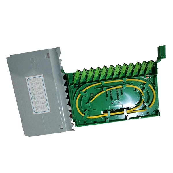
We show the manufacturing process of DIMI's Fiber Optic Terminal Box / FTTH Termination Box—from raw materials and injection molding to assembly, quality inspection, and packaging. If you're looking for a stable supplier for OEM/ODM and bulk orders, this video helps you un. Our extraordinary customer service, flexibility and skill in managing complex operations in lower cost Southeast Asia has made us the. On June 4, FiberHome Communications' subsidiary Thailand Ruisen Co. (hereinafter referred to as "Ruisen") held a groundbreaking ceremony for its optical fiber and cable manufacturing base. Officials said that the base has a construction area of about 72,000 square meters. The first phase of. Fiber optic termination box is made of ABS and ABS+PC material, which is a box for protecting optical fiber cable and pigtail welding at the termination of the optical cable. As a professional fiber optical terminal box manufacturer, UnitekFiber provides fiber terminal boxes with various waterproof. With the global fiber optic market reaching $6 billion and growing at 10% annually, the need for high-quality manufacturing solutions has never been greater. Single-mode fiber represents the pinnacle of long-distance optical transmission technology. However, the very characteristics that make fiber optic cables.
[PDF]

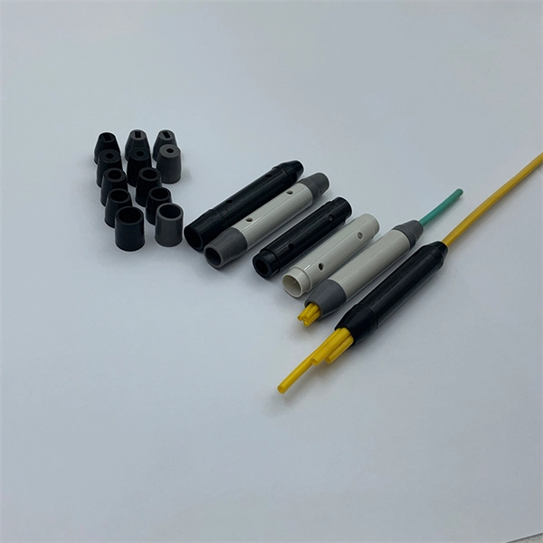
In all, there are five steps to manufacture a passive optical splitter. Each step requires strict control and management of various parameters like environment, temperature, and detailed precision on assembly and equipment. We will now provide a detailed introduction using PLC. A fiber optic splitter is a passive optical component that divides a single incoming optical signal into two or more outgoing signals, or combines multiple incoming signals into one. Unlike active devices (which require power), splitters operate without electricity, relying solely on the physics of. The Asia Pacific region (APAC) leads worldwide consumption of Planar Lightwave Circuit (PLC) splitter compact devices with a 68% share, followed by the Americas and the EMEA (Europe, Middle East, and Africa) region. The global PLC Fiber Optic Splitter market was valued at $4. 47 Billion USD in 2020. A fibre optic splitter like 1x2 Fiber Splitter is manufactured in five steps. Step 1: Component Preparation Generally, three components are required. The Evolution of Fiber Splitter Manufacturing Traditional fiber splitter production relied heavily on manual assembly and fused biconical taper (FBT) technology, which struggled to meet modern requirements for uniformity and miniaturization. It can divide the input optical signal into multiple output optical signals to meet the fiber optic access needs of multiple terminal devices.
[PDF]
FiberFin offers products specifically designed for the wide variety of sensor applications that POF is used in. There are three common methods for measuring external forces using plastic optical fiber. Optical fiber sensors have revolutionized the way we measure and monitor various physical and chemical parameters in different industries. These sensors utilize the properties of light to detect changes in the environment, making them highly sensitive and accurate. In this article, we will explore. Fiber Optic Sensors for Plastic Components by Application (Electronic Product, Automobile, Industrial Equipment, Others), by Types (Single-Tube, Double Tube, Multitube), by North America (United States, Canada, Mexico), by South America (Brazil, Argentina, Rest of South America), by Europe (United. While fiber optic cables can be used to connect remote sensors to electronic loggers or signal processors the same way that copper wires can, they can also be used as sensors themselves.
[PDF]

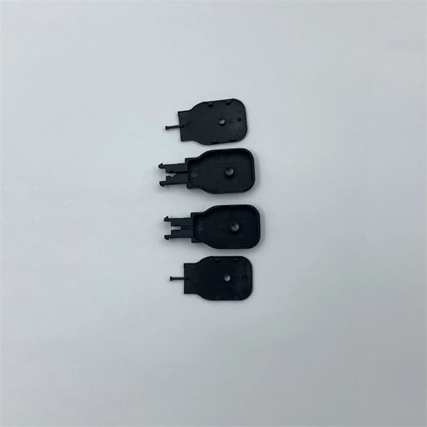
This article summarizes the research and development of a fully automated production process for optical fiber couplers, covering stages from fiber loading to glue packaging, which was demonstrated through the creation of a prototype and is expected to improve mass production . This article summarizes the research and development of a fully automated production process for optical fiber couplers, covering stages from fiber loading to glue packaging, which was demonstrated through the creation of a prototype and is expected to improve mass production . A fiber coupler is a passive optical device that manages the flow of light signals within an optical network. It functions by dividing a single incoming light path into multiple outgoing paths, or by combining light from several input paths into a single output fiber. They form the foundation of high-speed communications, ensuring that data, sensor signals, and laser outputs reach their destinations with minimal loss. Beyond simple. Fiber optic coupler is a lively type of passive components, and its basic function would be to achieve the optical power and fiber wavelength distribution.
[PDF]

Explore the top 10 PV combiner box manufacturers, their unique offerings, strengths, and market presence to make informed decisions for your solar energy systems. This section provides an overview for pv combiner boxes as well as their applications and principles. Here are the top-ranked pv combiner box companies as of April, 2026: 1. The ranking of PV combiner box manufacturers is based on several key criteria: Product Quality: Reliability and durability of products. Innovation: Advanced. Gain in-depth insights into Photovoltaic Combiner Box Market, projected to surge from USD 1. 5 billion in 2024 to USD 3. 8 billion by 2033, expanding at a CAGR of 10. Explore detailed market trends, growth drivers, and opportunities. 261 Combiner Box manufacturers are listed below. A complete list of component companies involved in Combiner Box production. 7% CAGR through 2029, driven by solar's 35% share in new power installations worldwide. When evaluating manufacturers, consider these critical factors: After analyzing 28 manufacturers across 15 technical parameters, these companies lead the. RAND PV (Photovoltaic “Solar” Electronics), a division of RAND Manufacturing Group, manufacturers NEMA 4X/ IP66 certified, UL approved customized solar assemblies, solar disconnect enclosures, load break devices (LBD), and solar combiner boxes. RAND PV UL-Listed 1741 Solar Combiners are designed.
[PDF]

Cratus Technologies, a Brillanz Group Company, proudly inaugurated Pakistan's largest Smart Theft-Resistant Telecom Cabinet manufacturing facility in Humak, Islamabad, spanning an area of 100,000 sq. This state-of-the-art 100,000 sq., the facility aims to enhance the country's telecom infrastructure by increasing domestic manufacturing. We're innovators in the 19” racks & cabinets industry, manufacturing and supplying IT infrastructure solutions throughout U. Today, Bolein is established as a global force and a one-stop shop for IT infrastructure solutions. We're industry leaders yet still. MEK Network Cabinets protect electrical components from harsh environm. Getting in touch with us is easy. So if you have a query, a doubt or an opinion to share, there are three easy ways to contact us. Pick up the phone and call us. You can also email to us for a prompt reply or write to us at. Pakistan Network Cabinet Suppliers Directory provides list of Pakistan Network Cabinet Suppliers & Exporters who wanted to export network cabinet from Pakistan. Don't know your target market? Wanted to market your Network Cabinet products globally? Join TradeFord. com to list your products online.
[PDF]

Outdoor Kitchen systems require structural durability, weather resistance, and long-term stability under changing environmental conditions. The manufacturing of outdoor kitchen cabinets involves a combination of material selection, precision fabrication, surface treatment, and quality control. Our manufacturing process blends traditional craftsmanship with advanced technology to create durable, stylish, and functional outdoor cabinetry. Partner with American Outdoor Cabinets as your expert outdoor kitchen manufacturer to deliver exceptional solutions tailored to your clients' need Our. hey have many advantages over wood. Wood for instance has to be finished, typically in mul�ple step processes, and in outdoor applica� ons typically fades, rots or warps. King StarBoard® ST and King StarBoard® WG are both environmentally stabilized and will not rust, delaminate, or ne re in a. Intelligent Manufacturing Ensures Precise Execution Once production begins, we treat every step as a critical part of quality assurance. Every technician follows detailed SOPs to ensure consistent results. This approach improves uniformity, strengthens traceability, and reduces human error. Dongguan shiru technology co. Was established in 2012. It is a company specializing in the production of outdoor projectors, three-proof intelligent constant-temperature cabinets, constant-temperature and constant-humidity cabinets, network cabinets, commercial display products, and sheet.
[PDF]

ADSS stands for All-Dielectric Self-Supporting. Let's break that down, because every word matters: All-Dielectric: It contains ZERO metal. No steel messenger wire, no aluminum armor. This means it is non-conductive. All-dielectric self-supporting (ADSS) cable is a type of optical fiber cable that is strong enough to support itself between structures without using conductive metal elements. It is used by electrical utility companies as a communications medium, installed along existing overhead transmission. 1. 1 The structure of ADSS optical cable ADSS is the abbreviation of All Dielectric Self-Supporting aerial optical cable in English, which means "all-dielectric self-supporting optical cable", and its structure does not contain any metal materials. AFL-ADSS® (All-Dielectric Self-Supporting) cable is ideal for installation in distribution as well as transmission environments. ADSS stands for All-Dielectric Self-Supporting. It is made entirely of glass, plastic, and aramid fibers. The result is that they can be hung in a straight line between poles or towers with no additional metallic. The ADSS Optical Cable is the full -scale self -inheritance optical cable. Composition: It consists of non -metallic enhanced core, fiber, aluminum foil shielding layer and non -metal protective cover. Features: no metal, tension resistance, self -inheritance, high insulation, inductiveness.
[PDF]
In summary, hermetic packaging uses metal and glass to provide tight protection for fragile optical chips, enabling them to withstand various usage environments. There are several specific packaging methods based on different device design requirements. An optical module housing is the protective outer shell that encloses the internal components of an optical transceiver module. These modules are essential for converting electrical signals into light signals and vice versa, forming the backbone of fiber optic communication systems in data centers. These modules are the essential translators, converting electrical signals to light and back again. But this sophisticated internal technology would be fragile, unreliable, and incompatible without its first line of defense and its primary interface: the optical module housing. This outer shell is. The main components of an optical transceiver can be generally divided into three parts: the externally visible housing, optoelectronic devices and PCBA. Uncover the metal casing of a transceiver module, you will find the inside components and sub-assemblies joint together. Optoelectronic devices. That is, metal medium communication represented by coaxial cables and network cables is gradually being replaced by optical fiber media.
[PDF]