The National Electrical Code (NEC) does not specify the maximum distance for a ground rod from a panel. However, the ground rod should be placed as close as possible to the panel to ensure an effective ground connection. Electrical clearances set the minimum safe distances for panels, overhead lines, pools, and buried wiring — and ignoring them has real consequences. (If these areas are accessible to other than pedestrian traffic, then one of the other conditions applies). Above finished grade or sidewalks, or from any platform or projection from which they. Learn key electrical code requirements for junction boxes, including sizing, grounding, materials, and clearance to ensure safety and efficiency. Whether it's a. The National Electrical Code (NEC) provides comprehensive safety standards for electrical installations, including requirements for electrical panels (main service panels and subpanels or breaker box). NEC Article 408 covers switchboards, switchgear, and Panelboards installation and applications. Following the manufacturer's installation instructions for the ground rod and.
[PDF]
In normal operating conditions the power consumption of a load is sometimes less than that indicated as its nominal power rating, a fairly common occurrence that justifies the application of an utilization facto.
[PDF]

This Code consists of the introduction, definitions, grounding rules, lists of referenced and bibliographic documents, and Parts 1, 2, 3, and 4 of the 2023 Edition of the National Electrical Safety Code. The Institute of Electrical and Electronics Engineers, Inc. 3 Park Avenue, New York, NY. Climbing Space is an unobstructed, vertical space along the side or corner of the pole. In gen-eral, it consists of an imaginary box, 30-inches square, extending at least 40 inches above the highest communications cable or other facility and 40 inches below the lowest communications cable or other. The Fiber Optic Association, Inc. (FOA) was founded in 1995 to help develop the workforce to build the fiber optic networks to support a rapid expansion in communications and the Internet. The charter of the FOA was to promote professionalism in fiber optics through education, certification, and. There are a number of ways of finding out more about cabling standards. You can buy a complete copy of the EIA/TIA or ISO/IEC standards which can be very expensive and wade through page after page of standards language. You can also get catalogs and/or visit the websites of a number of cabling. to n utral comm.
[PDF]

This AutoCAD DWG file includes a complete Single Line Diagram (SLD) of a Distribution Board, showing circuit breakers, wiring connections, and load distribution for lighting, power, and mechanical systems. An electrical panel box, also known as a breaker box or a distribution board, is a crucial component of any electrical system. It serves as a central hub for distributing electricity throughout a building, ensuring that power is delivered safely and efficiently to all the required locations. Whether you're an electrician or a DIY enthusiast, this guide will help you understand the basics of home electrical distribution. What is Distribution Board? Distribution board. Welcome to our channel @Electricalgenius In this video, we'll take you through a detailed step-by-step guide on wiring a home distribution DB (Distribution Board) box. A distribution board (also known as a service panel or breaker box) is a centralized collection of circuit breakers, fuses, and/or relays used to control and protect the wiring in a home. The diagram. To understand how a breaker box works, it is helpful to have a wiring diagram that shows the connections between the various components. At the heart of a breaker box is the main breaker, which controls the flow of electricity from the utility into the building. This breaker is connected to a.
[PDF]
What does it take to make an effective explosion-proof junction box or cabinet? An incredible mechanical engineering design is what you need. Design for such enclosures and storage boxes differ with each m.
[PDF]

This report lists the top Sri Lanka Telecom Tower companies based on the 2023 & 2024 market share reports. Mordor Intelligence expert advisors conducted extensive research and identified these brands to be the leaders in the Sri Lanka Telecom Tower . Monopole towers are constructed from steel or concrete and can range in height from 30 meters to over 100 meters. It is a type of lattice tower that is commonly used in areas where space is limited or aesthetics are important, such as urban or suburban environments. Need More Details on Market Players and. We are an integrated service provider in Telecom, Energy and Civil Infrastructure. Our capabilities range from providing end to end services for telecom tower construction, technical enhancements and maintenance on the towers. We also provide renewable energy solutions and have strong expertise. SGH TowerCo Ltd., the telecommunications and network infrastructure arm of Supreme Global Holdings (SGH), has announced that it has been officially granted a Telecommunications Infrastructure Services Licence by the Telecommunications Regulatory Commission of Sri Lanka (TRCSL). Preview of Communications tower businesses in Sri Lanka **. **** Athurugiriya Clock T. **** Sri Lanka 🇱🇰🇯🇵🌄🌍🌻. **** ITN. We are the pioneers in providing lightweight aluminum rooftop modular tower solutions from Europe.
[PDF]

In this comprehensive guide, we'll walk through the best practices for installing various types of fiber optic cable, from patch cords to distribution fiber, and provide practical tips to ensure a successful installation. This article will guide you through the necessary tools, materials, and methods on how to connect fiber optic cables effectively, ensuring you achieve optimal performance from your fiber optic network. Have a network installation project? Fiber Optic Cables: The primary medium for your connections. Fiber optic cable is a type of cable that contains one or more optical fibers—thin, flexible strands of glass or plastic that are designed to transmit light signals. These cables are used for transmitting data over long distances with high bandwidth and low signal loss. Before connecting any fiber cable, you need to assemble the proper preparation tools: With the right tools in hand, follow these key steps to achieve reliable fiber connections: 1. The number one cause of signal loss in optical fiber installations is dirt on. In this video, we'll guide you through preparing and terminating fiber optic cables using SimplyFiber products, known for their high quality, ease of use, and reliability. more Audio tracks for some languages were automatically generated. Why Opt for Fiber Optics? Fiber optic cables have skyrocketed in.
[PDF]

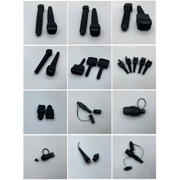
A fiber pigtail is a short optical fiber cable with a connector pre-installed on one end and a bare fiber on the other. It acts as a bridge between optical fibers and devices, making it a vital part of network termination, splicing, and patching processes. In the world of fiber optic communications, reliability and precision are everything. As networks scale to support FTTH rollouts, 5G base stations, and hyperscale data centers, the way fiber is terminated and managed at every endpoint can determine whether a project succeeds or fails. One component. Executive Summary: A fiber optic pigtail is one of the most commonly specified yet least understood components in structured cabling. Get the wrong connector type, the wrong polish, or skip proper fusion splicing technique—and you're looking at elevated signal loss, increased back reflection, and a. ■ What is a fiber optic pigtail cable? A pigtail fiber indicates a short length of optical fiber cable that has a pigtail connector (for example, SC, FC, ST, LC, etc. ) fitted on one end and the other end undressed (for connection through fusion or splicing) to the main fiber optic cable. What does fiber optic pigtail mean? A fiber optic pigtail works like a bridge between two different connection methods. It is usually suitable for field termination using a mechanical or fusion splicer.
[PDF]

This video shows real on-site footage of electrical installation, demonstrating safe and standardized wiring methods used by professionals. more Learn how to wire a distribution box step by step! This video shows real on-site footage of. Understanding the wiring diagram of an electrical panel box is essential for electricians and homeowners alike, as it allows them to troubleshoot any electrical issues, carry out repairs, or make additions to the system. The electrical panel box wiring diagram provides a visual representation of. A distribution box is the heart of any electrical system. It takes the incoming power and safely distributes it to different circuits throughout your building. Whether in a home or an industrial facility, this box keeps your electrical setup organized, functional, and efficient. However, the key to. In this video, we'll walk you through the process of wiring a home distribution box with a detailed connection diagram. It has three categories: residential, commercial and industrial electrical distribution boxes, all of which play important roles in their respective electrical. It is responsible for distributing electricity throughout a building, ensuring that each circuit receives the proper amount of power. To understand how a breaker box works, it is helpful to have a wiring diagram that shows the connections between the various components. At the heart of a breaker.
[PDF]

Thailand's government says that it will press ahead with its plan to build a “land bridge” in the country's south, creating a link between the Indian and Pacific oceans that will bypass the Strait of Malacca. Prime Minister Anutin Charnvirakul has confirmed that the government will advance the Land Bridge mega-project, now valued at about 997. 7 billion baht, to strengthen Thailand's long-term growth. The project aims to connect deep-sea ports in Ranong and Chumphon via supporting infrastructure under a. BANGKOK: Thailand's Deputy Prime Minister Phiphat Ratchakitprakarn told members of the media on Monday (April 20) that it is going ahead with a land bridge that would connect the Indian and Pacific oceans. Significantly, the long-planned bridge will bypass the Strait of Malacca, which has been in. Thailand's Land Bridge is back on the cabinet agenda, and the version being prepared is materially different from the one Srettha's government marketed in 2024. The port of Ranong in southern Thailand. Thailand is moving forward with a transformative infrastructure initiative: the Thailand Land Bridge, valued at nearly 1. Thailand's ambitious plan to construct a 90-kilometer land bridge across its southern region has garnered attention.
[PDF]

We are the one-stop you can reach for getting a high-quality, and customized range of Electrical Panels, Cable Trays, Rising Mains and more as per the customer requirements. We are loaded with all the advanced resources and have a team of professionals to handle your bulk queries. With non-slip treaded covers to optimize slip resistance, the BKRS Walkable Cable Tray ensures your cables get the best defense. Chalfant Ladder Cable Tray Systems are ideal for indoor and outdoor cable management. They provide reliability, ease of installation, and cost savings both initially and. If you are searching for Electrical Cable Tray in Samoa, Brilltech Engineers Pvt. is a trusted brand that you can rely on. Being one of the. Tradewheel. com provides buyers with a free hand to explore customized cable tray solutions offered by manufacturers all across the globe. For over a decade, the platform has assisted millions of buyers in finding reliable products and suppliers who can thoroughly distribute high-quality products on. The trays inside buildings can be installed independently or attached to various building structures and pipe gallery supports. The trays inside buildings can be installed independently or attached to various building structures and pipe gallery supports, reflecting characteristics such as simple. This guide offers an in-depth look at some of the top cable tray manufacturers worldwide, broken down by region: Europe, South America, North America, Africa, and Asia.
[PDF]

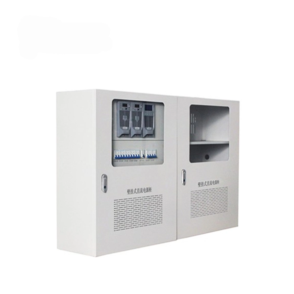
We are a professional Android TV Box manufacturer, offering factory-direct prices and stable product quality. Special discounts for bulk orders. OEM/ODM orders are welcome, including logo printing, packaging design, firmware customization, and other tailored solutions. BlueBox is a leading corporate venturing firm in Latin America that supports entrepreneurs and corporations in building impactful multinational enterprises. Their focus on acceleration and innovation positions them as a key player in fostering connections between startups and corporations. Bluebox. Manufacturer of Custom Electrical Enclosures, Electrical Boxes, and Electrical Cabinets. Capabilities include: cutting, forming, welding, powder coating, screen printing. Durable and Waterproof Design: Our Mexico home electrical panel board distribution boxes and switches are designed with a robust IP67 rating, ensuring they are waterproof and dustproof, making them perfect for outdoor electronic equipment applications, as mentioned by John, an electronics engineer. Grupo Gondi ranks as one of the top corrugated carton box manufacturers in Mexico for B2B clients. The company runs 4 paper mills, 9 corrugated packaging plants, and 6 high-graphic facilities across the country. You get large-scale packaging solutions built from recycled paper and cardboard. Our Android TV boxes are CE.
[PDF]
You are looking at $0. The price swing usually depends on the fiber count (e., 12-core vs 96-core) and brand. Generic glass is cheap; premium glass (like Corning) costs more but guarantees lower attenuation. You are looking at $0. It is composed of 6 multimode fibers (50 micron core) inside a water blocking Aramid yarn wrapped in a black PVC outer jacket. Commercial building installations with 100-200 network drops generally range from $15,000 to $30,000. Single-mode fiber costs less per foot than multimode fiber, but it requires more. The unit cost of fiber optic cables can vary from $0. Here's a general pricing reference: Cable TypePrice Range (USD/meter)Simplex / Duplex Indoor Cable$0. 30Single-mode Outdoor Cable$0. 50Multimode (OM1/OM2/OM3)$0. 10 –. The price of fiber optic cabling depends on cable type, length, installation method, and surrounding materials. Typical costs hinge on fiber count, indoor versus outdoor use, and whether trenching, splicing, or termination is required.
[PDF]