These towering structures, also known as electric pylons or transmission lattice towers, form the backbone of the communication infrastructure, enabling the seamless flow of data and information across vast distances. In the fast-paced world of communication and technology, the role of iron towers in the transmission and distribution of signals cannot be overstated. Found at the base of cell towers, rooftops, or even disguised in street furniture, the BTS comprises three critical subsystems: A. Power System: Keeping the Network Alive 24/7 Power is essential for uninterrupted service. These towering structures may seem simple at first glance, but they are complex systems designed to facilitate the seamless. Telecommunication Towers are tall, engineered structures designed to support the antennas and electronic equipment that power wireless communication networks. As essential infrastructure, these towers form the backbone for 3G, 4G, and 5G networks, ensuring reliable connectivity across both urban. Telecommunication towers are the unsung heroes in a world powered by instant communication and data exchange. Despite their. Introduction : The wireless network that provides voice and data services to cell phone users is known as a cell phone network or cellular network. In this tutorial, we will explore different types of towers including monopole, lattice, guyed, stealth, and rooftop towers used for seamless wireless.
[PDF]

In the drawing that is not at 1:1 scale, find an object or line whose length you know. Start the scaling command with SC (or SCALE). Make a selection for the objects that need to be included in the scaling operation. Click in the drawing for the first point of the. AutoCAD 2D drawings are commonly drawn in model space at a 1:1 scale (full-size). In other words, a 12-foot wall is drawn at that size. The drawings are then plotted or printed at a plot "scale" that accurately resizes the model objects to fit on paper at a given scale such as 1/8" = 1'. In some. To scale a CAD drawing object that has been inserted into another application, you typically access its properties to adjust the display size relative to the page or other elements. Scaling a CAD drawing, particularly when it's embedded or linked in another document like a technical diagram or. In this video, I'll show you how to scale any object to an exact size in AutoCAD—perfect for resizing blocks, drawings, or imported items to match real-world dimensions. This process ensures that all elements in your designs are proportionally accurate, allowing for efficient layouts and designs. Selecting the Object. The below table shows you how to set the scale within paper space in AutoCAD to the correct scales. Scaling refers to the proportionate resizing of an object within a drawing. In 2D CAD, it ensures that objects fit within the drawing space while maintaining real-world proportions.
[PDF]

com is a free cell tower locator that maps over 2. Use the interactive map above to find cell towers near you — including 5G, 4G LTE, and legacy towers — with precise GPS coordinates sourced from the FCC database. Search and locate over 2. 8 million cell tower locations, cell phone towers, and 5G towers across the United States. Search, analyze, and export detailed information about mobile network infrastructure, cell phone towers, and telecommunications sites using official FCC data. What is. WARNING: Setting the type to DAS will cause the tower to split into individual cells. Explore network coverage by operator and country, and more! What is OpenCelliD? OpenCelliD is working towards creating an open cellular dataset that is driven and inspired by the community. This cellular data is used for a multitude of commercial/private purposes by patrons worldwide. Fix dead zones, compare carriers, and get the signal you need. Everything you need to find, navigate to, and understand cell towers. See every cell tower around you plotted on an.
[PDF]

Download a comprehensive set of Cable Tray Installation CAD Blocks in DWG format, ideal for electrical engineers, MEP designers, and industrial layout planners. Discover all CAD files of the "Cable trays" category from Supplier-Certified Catalogs ✅ SOLIDWORKS, Inventor, Creo, CATIA, Solid Edge, autoCAD, Revit and many more CAD software but also as STEP, STL, IGES, STL, DWG, DXF and more neutral CAD formats. Electrical cable tray layout is a ready-to-use CAD block perfect for building services, industrial setups, and electrical projects. This cable tray CAD block is compatible with AutoCAD and other DWG-supported software, allowing precise placement and easy integration into your designs. Save time and. Download this FREE 2D CAD drawing of CABLE TRAYS including various widths. This autocad drawing can be used in your mechanical design CAD drawings. dwg format) Our CAD drawings are purged to keep the files. Already Subscribed? Download free cable trays in DWG or CAD block format. This collection includes installation details for ladder trays, perforated trays, solid-bottom trays, and wire mesh trays, along with. We already have a software for 3D cable route planning “Caneco One” which allows the import of DWG files. However, Caneco does not recognize any Plant 3D properties from the file such as instrument TAG. Is there a way to perform 3D cable route planning within the AutoCAD suite? Or are there.
[PDF]

This free DWG file includes a well-organized collection of switches, sockets, DB symbols, lighting points, junction boxes, and earthing details. Along with that, it provides installation guidelines such as conduit fixing, wiring connections, and mounting heights. Download free collection of AutoCAD details for electrical systems. All installation details for electrical design of building including the various systems in electrical field such as power distribution, lighting, earthing, electrical cables, distribution boards and many other electrical system. Development of an electrical installation that contains detail from well to ground; box with symbols; electrical outlet installation detail; distribution board and technical specifications. If you are working on Electrical Shop Drawings or preparing as-built layouts, having a complete set of standard AutoCAD electrical symbols and installation details can save you hours of drafting time. Detailed cutaway of the lighting box. Our collection features high-quality resources from top manufacturers, available in both 2D and 3D formats to support your electrical projects. This. Free CAD and BIM blocks library - content for AutoCAD, AutoCAD LT, Revit, Inventor, Fusion 360 and other 2D and 3D CAD applications by Autodesk. CAD blocks and files can be downloaded in the formats DWG, RFA, IPT, F3D. You can exchange useful blocks and symbols with other CAD and BIM users.
[PDF]
The hot and cold aisles in the data center are part of an energy-efficient layout for server racksand other computing equipment. The goal of a hot/cold aisle configuration is to manage airflow in a way that c.
[PDF]

An optical network is a communication system that leverages light to convey information across distances, encoding data into rapid flashes of light instead of relying on electrical voltage changes. At the heart of this ecosystem lies the Optical Transport Network (OTN) — a framework defined by the ITU-T (notably G. 709) that has become the foundation for modern optical communications. This method allows engineers to manage the exponential growth in global data traffic generated by. A passive optical network (PON) is a system commonly used by telecommunications network providers that brings fiber optic cabling and signals all or most of the way to the end user. Depending on where the PON terminates, the system can be described as fiber to the curb, fiber to the building or. An Optical Transport Network (OTN) is a transmission network based on wavelength division multiplexing (WDM) technology. It is a specific type of transmission network that transmits data and manages it using optical signals. OTN is built on a series of protocols, including G. It is designed to provide a high-speed, scalable, and reliable infrastructure for the transmission of data between different network nodes. While there are many subtle differences, a clear distinction between active optical networking and PON topology is PON's use of a.
[PDF]
Modern fiber-optic communication systems generally include optical transmitters that convert electrical signals into optical signals, optical fiber cables to carry the signal, optical amplifiers, and optical receivers to convert the signal back into an electrical signal. The information transmitted is typically digital information generated by computers or telephone systems. Transmitters The most commo. OverviewFiber-optic communication is a form of for from one place to another by sending pulses of or through an. The light is a form of. First developed in the 1970s, fiber-optics have revolutionized the industry and have played a major role in the advent of the. Because of its advantages over electrical transmission, optical fiber. is used by telecommunications companies to transmit telephone signals, Internet communication and cable television signals. It is also used in other industries, including medical, defense, governmen.
[PDF]

When Batelco was first founded in 1981, Bahrain already had 45,627 telephone lines in use. By 1982, the number reached 50,000. Batelco enjoyed being a monopoly in the telecommunications sector for the next two. Telecommunications in Bahrain are provided by the Bahrain Telecommunications Company, trading as Batelco, as well as other companies such as Zain and STC. Prior to 1981 telecommunications services were provided by two separate departments: national services were provided by the Bahrain. Explore the evolution of BNET in Bahrain, a testament to the nation's commitment to advancing telecommunications infrastructure and connectivity. BNET won the Gigacity Excellence Award at the WBBA Broadband Excellence Awards 2024! Learn about BNET's evolution and its journey to provide advanced. alth, and to maintaining national competitive advantage. Change in information and telecommunications technology (ICT) has accelerated over the last two ecades, and these two areas have increasingly converged. Since then, other companies such as Zain and VIVA have entered the telecommunications sector. During the same year, Optical fibres and cables were the 479th most exported product (out of 3,333) in Bahrain. In 2024, the main destinations of.
[PDF]

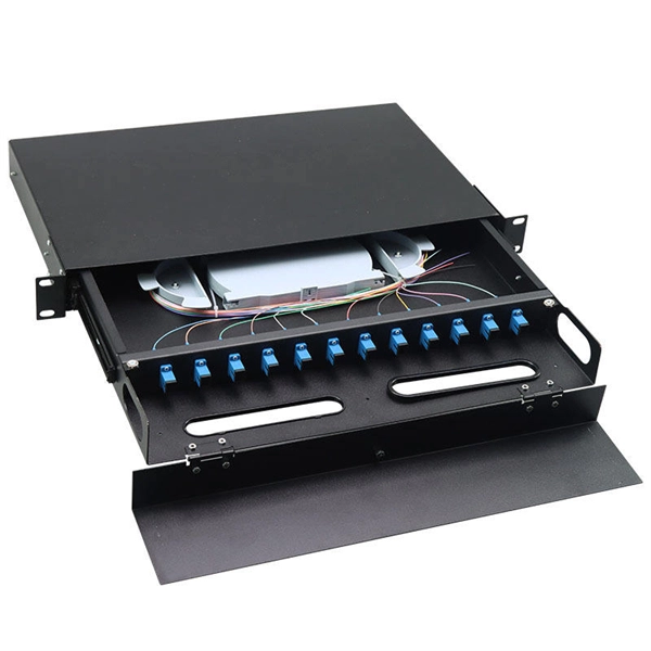
They function as intermediate distribution points between: The enclosure itself does not process optical signals. Its role is structural and operational rather than active transmission control. Different box structures support different deployment layers inside FTTH and. In the complex architecture of fiber optic networks, the Optical Distribution Frame (ODF) serves as the linchpin for organizing, protecting, and distributing optical signals. Whether in data centers, telecom central offices, or enterprise network rooms, ODFs enable efficient fiber management. A Fiber Optic Distribution Box is a key device in fiber optic communication networks, used for centralized management, distribution, and protection of fiber optic connections. As an important node in fiber optic access networks (such as FTTH) and backbone networks, it ensures efficient transmission. An optical distribution frame (ODF) is a crucial component in the telecommunication industry, specifically in the area of fiber optic networks. Its role is structural and. This complete guide explores everything you need to know about ODFs — from their structure, types, and key components, to installation best practices and modern design trends. It serves as a merging point for the optical fibers, where connections are consolidated and routed, thus minimizing signal attenuation. The ODF includes.
[PDF]

A fiber is used to support G. 691 with a maximum rate of STM-16 or 10Gbit/s and a maximum transmission distance of 40 km (Ethernet) and STM-256 for G. This document outlines the specifications for a single-mode optical fiber and cable designed for use around the 1310 nm zero-dispersion wavelength, suitable for both the 1310 nm and 1550 nm regions, and compatible with analogue and digital transmission. It details the fiber's geometrical, optical. G. 652 is an international standard that describes the geometrical, mechanical, and transmission attributes of a single-mode optical fibre and cable, developed by the Standardization Sector of the International Telecommunication Union (ITU-T) that specifies the most popular type of single-mode. G. 652 optical fiber is a kind of optical fiber that is widely used in the network. 652 is mainly based on the requirements of PMD and the attenuation requirements at 1383nm. 652D is the type of optical fiber in the optical cable, which represents non-dispersion-shifted single-mode fiber, and is currently the most widely used single-mode fiber in China. This article will provide a detailed introduction to the structure, characteristics, and applications of standard single-mode fiber. G652 is a specification for optical fiber cables. It is part of the International Telecommunication Union (ITU-T) G.
[PDF]

The solution is to unplug the fiber and reinsert it into the SFP module interface until a “click” sound is heard, indicating the fiber connector and SFP module are properly connected. Contamination or damage on the fiber end face requires the use of a fiber end-face inspection. The physics of noise in optical communication links is of great interest in the design of fiber optic communication systems. The origins of noise in. Optical transceivers—such as SFP, QSFP, and OSFP transceivers —are essential components in high-speed data center and enterprise networks. These fiber optical transceivers convert electrical signals into light and back, enabling long-range, high-bandwidth communication over fiber optic links. Think of it. Optical transmission is vulnerable to various sources of signal degradation, including chromatic dispersion, modal dispersion, polarization mode dispersion, and noise. In the real world, an optical receiver's ability to resolve information is impacted by the presence of noise. They are the foundation of the network world. SFP optical modules are precision devices, and various faults may inevitably occur during operation. These faults can. Noise and Signal Interference in Optical Fiber Transmission Systems is a compendium on specific topics within optical fiber transmission and the optimization process of the system design. It offers comprehensive treatment of noise and intersymbol interference (ISI) components affecting optical.
[PDF]
An optical transceiver module, often simply called an optical module, acts as a signal conversion interface in fiber optic networks. It transforms high volumes of electrical signals into optical signals for transmission over fiber cables, or reverses the process at the receiving. As an essential component of optical fiber communication, optical modules are optoelectronic devices that facilitate the conversion between optical and electrical signals during the transmission process. Operating at the physical layer of the OSI model, optical modules are core devices in optical. An optical module is a typically hot-pluggable optical transceiver used in high-bandwidth data communications applications. Its primary function is to achieve optoelectronic conversion by converting electrical signals into optical signals and vice versa. If you're dealing with data centers, telecommunications, or AI networking, grasping the key parameters of an optical. What is an Optical Module? The Ultimate Guide to Principles, Types, and Troubleshooting Optical Modules (also known as Optical Transceivers) are critical components in fiber optic communication systems. Among various optical module form factors, SFP (Small Form-Factor Pluggable).
[PDF]