In this video, we'll walk you through the process of wiring a home distribution box with a detailed connection diagram. Whether you're an electrician or a DIY enthusiast, this guide will help you understand the basics of home electrical distribution. more Welcome to our channel! In this video. This guide provides step-by-step instructions for connecting a distribution box and highlights key factors to consider during installation. What Is a Distribution Box? A distribution box, also known as an electrical distribution board, is a critical component in electrical systems. It takes the incoming power and safely distributes it to different circuits throughout your building. However, the key to. A junction box provides a necessary protective enclosure for all electrical wire splices and connections, which must never be left exposed within a wall or ceiling. It serves as a central hub for distributing electricity throughout a building, ensuring that power is delivered safely and efficiently to all the required locations.
[PDF]

This video shows real on-site footage of electrical installation, demonstrating safe and standardized wiring methods used by professionals. But first, the rules: Turn off the power when working with electricity. Make sure the power's off using a non-contact voltage tester or multimeter. One final tip: Get into the habit of making connections in this. How to make proper & safe electrical wiring splices & connections: This article answers basic questions about how splices (connections between two or more electrical wires) are made to connect & secure electrical wires together in residential or commercial building electrical wiring systems. We. There must be a simpler way to connect the bare wire inside a duplex box. When I run a circuit into a duplex recepticle box, to an outlet, then back out again on to the next box, I wonder how to connect the bare wires together and at the same time, to the recepticle. In the past, I have cut a 6". How to properly bring bare #6 copper into service panel? I've got a small service panel in my shed (6 circuits). I drove 2 8' grounding rods outside and have routed continuous #6 bare copper into the shed. What kind of. Before installation, it's important to know what makes up a distribution box. Let's break it down into two main parts: the outer shell and the electrical parts inside. The enclosure protects the electrical components from water, dust, and damage. When choosing one, check the IP or NEMA rating.
[PDF]

The easiest way is to use the $3 "spec-grade" receptacles which come in a box instead of loose in a bin. If it's just black and white wires with a cloth or plastic covering and no ground wire you'd need a retroit grounding wire to have grounded outlets. A clearer picture of the cable entering will help. Can you post photos that show clearly where the cables enter the box at, please? @Traveler No!. The process of wiring a small breaker box, often called a subpanel, is a common task when adding power to a detached structure like a shed, garage, or a major home addition. These smaller distribution centers are designed to take power from a larger main service panel and distribute it locally to. How do I wire a mini circuit breaker distribution box that doesn't have bus bars? I have a circuit going to my shed from my house and I want to have two separate breakers inside the shed (one for outlets, one for other stuff) so I bought this from amazon (Amazon. com: 2 Way Distribution Box Circuit. In this video, we'll walk you through the process of wiring a home distribution box with a detailed connection diagram. more Welcome to our channel! In this video. Connecting a distribution box involves several steps to ensure proper electrical flow. But first, the rules: Turn off the power when working with electricity. Make sure the power's off using a non-contact voltage tester or multimeter. One final tip: Get into the habit of making connections in this.
[PDF]

Connect all three phases and the neutral wire to the input of the residual-current device. An overcurrent circuit breaker is connected at the output to each phase. It is an electrical protective device that protects electrical circuits and devices from some electrical faults such as leakage faults, electrical shock, current unbalance due to equipment failure, etc. It works on the principle of sensing residual current which is why it is called a residual. Distribution board is a safe system designed for house or building that included protective devices, isolatorswitches, circuit breaker and fuses to connect safely the cables and wires to the sub circuits and final sub circuits including their associated Live (Phase) Neutral and Earth conductors. A residual-current device (RCD), protects the user of the installation against electric shock. Therefore, not only the efficiency and reliability, but also the proper connection of this device is important. Make sure you have watched the linked video below on how to strip and prepare wires and cables for termination before you do any wiring:. more Audio tracks for some languages were automatically generated. This guide provides a detailed, professional procedure for installing a Residual Current Circuit Breaker (RCCB)—a device essential for protecting people from the severe danger of electric shock. The steps outlined here are fundamental to ensuring the RCCB functions correctly as a life-saving.
[PDF]
Connect the input and output wires to the corresponding terminals of the distribution box. Then press the wire onto the terminal with a wire stripper, or tighten the wire with screws. This step is very crucial and can not bear any faults!. In this video, we'll walk you through the process of wiring a home distribution box with a detailed connection diagram. more Welcome to our channel! In this video. This guide provides step-by-step instructions for connecting a distribution box and highlights key factors to consider during installation. What Is a Distribution Box? A distribution box, also known as an electrical distribution board, is a critical component in electrical systems. It serves as a central hub for distributing electricity throughout a building, ensuring that power is delivered safely and efficiently to all the required locations. It is usually equipped with circuit breakers, fuses, terminal connectors, and other components.
[PDF]

In this video, we'll walk you through the process of wiring a home distribution box with a detailed connection diagram. Whether you're an electrician or a DIY enthusiast, this guide will help you understand the basics of home electrical distribution. more Welcome to our channel! In this video. A distribution box is the heart of any electrical system. It takes the incoming power and safely distributes it to different circuits throughout your building. However, the key to. Material preparation: Prepare the required circuit breakers, wires, wiring ties and other materials, and ensure that they meet the design drawings and installation requirements. Location determination: Determine the installation position of the circuit breaker according to the position of the. In modern electrical systems, cable distribution boxes (also known as electrical distribution boxes or distribution boxes) play a crucial role as the key hub for managing, distributing, and protecting circuits. Whether it is residential buildings, commercial facilities or industrial sites, the. Hey, in this article we are going to see the Single Phase Distribution Box Wiring Diagram and Connection Procedure. A distribution board or distribution box is where the main power supply is distributed to multiple loads.
[PDF]

Pictures and step-by-step instruction for splicing household electrical wiring to extend a circuit. Connecting wires to your home distribution box? See how electricians do it professionally! From selecting the right wire gauge to safely connecting the main. A distribution board or distribution box is where the main power supply is distributed to multiple loads. And all the switching and protective devices are installed in the distribution box. Single Phase Distribution Box generally consists of Double Pole MCBs, Single Pole MCBs, and RCCBs. Covers wiring, placement, standards, and expert tips for a compliant setup. It takes the incoming power and safely distributes it to different circuits throughout your building. Whether you're an electrician or a DIY enthusiast, this guide will help you understand the basics of home electrical distribution. What is Distribution Board? Distribution board. Always begin with disconnecting the main supply before accessing any enclosure containing distribution components. This prevents arc faults and ensures safety when modifying or inspecting current paths. Inside the service housing, line conductors from the utility feed typically enter through the. A plastic connector, called a wire nut, is used to insulate and secure the splice. Wire splice connections must be housed inside a covered electrical box, known as a junction box. A junction box is usually square.
[PDF]

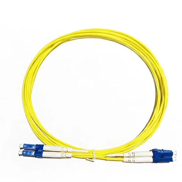
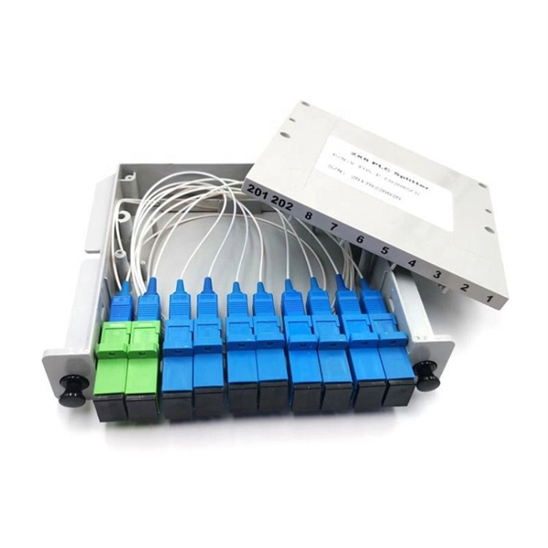
The most common fiber splice closure sealing methods include heat-shrink, mechanical, and gel-based sealing. While they all share the goal of isolating external factors, they achieve this in different ways. Gel seals utilize a soft gel material that adheres tightly to the cable. Another type of closure is a hybrid of splices and a patch panel. These are often used with fiber to the home (FTTH) networks where drop cables to individual subscribers are factory made preterminated cables and just require plugging in connectors - no splicing required. Here is two examples of. Fiber optic closures protect and organize cable splices, ensuring long-term stability in both outdoor and indoor networks. This guide explains their functions, types, and selection criteria, while showing how FiberMania's OEM customization helps achieve higher reliability and efficiency in modern. In modern FTTx and PON networks, fiber optic splice closures are the enclosures that protect fiber splice points from moisture, dust, and physical stress. Installing a fiber optic splice closure efficiently and effectively requires attention to detail and. 1 Sealing of the fiber optic splice closure (1) Clean the sealing groove around the joint box with alcohol cotton/wipes. (2) Insert the sealing strip into the sealing groove of the lower half of the joint box. This guide is written to provide a complete and engineering-oriented understanding of fiber optic splice closures—from basic concepts and.
[PDF]

In this short tutorial, I'll show you the tools, steps, and pro tips to fix wall boxes neatly for switches, sockets, and lights. Learn how to install a distribution box safely and correctly. Covers wiring, placement, standards, and expert tips for a compliant setup. It takes the incoming power and safely distributes it to different circuits throughout your building. It has three categories: residential, commercial and industrial electrical distribution boxes, all of which play important roles in their respective electrical. Standard procedures for lighting and socket installation provide safety, efficiency, and adherence to electrical codes. This post includes designing, wiring, mounting, testing, and safety inspections to guarantee that the electrical system operates properly and reliably. Material preparation: Prepare the required circuit breakers, wires, wiring ties and other materials, and ensure that they meet the design drawings and installation requirements. Perfect for beginners and electricians improving their skills. more Learn how to install electrical boxes. In modern electrical systems, cable distribution boxes (also known as electrical distribution boxes or distribution boxes) play a crucial role as the key hub for managing, distributing, and protecting circuits. Whether it is residential buildings, commercial facilities or industrial sites, the.
[PDF]
This step by step fiber cutting guide shows you the correct tools and techniques for fiber opt. Executive Summary: A fiber optic pigtail is one of the most commonly specified yet least understood components in structured cabling. Get the wrong connector type, the wrong polish, or skip proper fusion splicing technique—and you're looking at elevated signal loss, increased back reflection, and a. Splicing thick cables correctly is essential to ensure efficient and safe transmission of electrical current. Improper splicing can cause a number of problems, such as loss of power, equipment damage, fire risk, and even personal injury. Regardless of the type of fiber network you're deploying, be it for telecom, enterprise data centers, or smart city infrastructure, fusion splicing provides the benefits of. Think of a fiber optic cable splice as the seamless stitching that keeps data flowing through the delicate threads of a network—like a master tailor joining fabric with precision. Whether repairing a broken cable or extending a fiber run, fiber optic splicing ensures light signals travel. This guide reveals the secrets to fusion splicing with little fluff—just proven, straightforward techniques refined from years of work in the field. The guide provides the complete workflow, covering safety precautions, tool selection, fiber preparation, fusion operation, quality control, and.
[PDF]

Electrical clearances are the minimum separation distances the National Electrical Code (NEC) requires between wiring, panels, overhead conductors, and everything around them. These rules exist to prevent electrocution, fire, and equipment damage. Dedicated space: The space equal to the width and depth of electrical equipment in addition to the space extending. However, a common question arises: how many wires can you safely put in an electrical box? The answer might surprise you, as it's not just a simple number. In this comprehensive guide, we'll delve into the factors that determine the maximum number of wires, the risks of overcrowding, and provide. The National Electrical Code (NEC) governs electrical junction box rules. These rules define when you must install a box, how large it must be, how you must install it, and how inspectors evaluate compliance. This guide breaks down the actual rules inspectors check — with calculations and. Mandatory separation distances between electrical components and gas lines are governed by national and local codes prioritizing public safety. These regulations minimize potential hazards that arise when the two utility systems are in close proximity during new construction or renovation. Adhering. Electrical panel clearance is a critical aspect of workplace safety, ensuring that electrical equipment is accessible and maintainable without risk of injury.
[PDF]
This guide will walk you through every step of the process, from selecting the right materials to securing connections and ensuring safety. Whether you're a seasoned professional or an enthusiastic DIYer, our detailed instructions will equip you with the knowledge and confidence to tackle this. Learn how to properly install an electrical box safely and efficiently. In this step-by-step tutorial, we'll cover: ✅ Tools you need. Covers wiring, placement, standards, and expert tips for a compliant setup. A distribution box is the heart of any electrical system. It takes the incoming power and safely distributes it to different circuits throughout your building. A neutral bar kit is a fundamental component within an electrical service panel, often called a breaker box, designed to manage the flow of electricity in a home or building. This metal strip serves as the termination point for all neutral conductors from the branch circuits. By consolidating these. Before starting the installation, finding a proper place for putting the distribution box is crucial, because it largely decides the safety and convenience of maintenance. Let's see what factors need to be taken care of when choosing the installation place. Beginning of dialog window. Escape will cancel and close the window.
[PDF]

In this step-by-step tutorial, we show you exactly how to place a fusion splice safely and securely inside a Coyote fiber optic splice enclosure. Fiber cable splicing is a critical step in building reliable fiber optic networks. Whether in data centers, telecom rooms, or outdoor FTTx deployments, proper splicing inside a fiber enclosure ensures low signal loss, long-term stability, and easy maintenance. This guide explains what fiber cable. Think of a fiber optic cable splice as the seamless stitching that keeps data flowing through the delicate threads of a network—like a master tailor joining fabric with precision. Whether repairing a broken cable or extending a fiber run, fiber optic splicing ensures light signals travel. In addition to the outer skin of the optical cable (if any, please remove the shielding and armoring) and then remove each wrapping layer until the loose tube is exposed. Make sure you read and understand this instruction as well as instructions provided with related assemblies before. In this guide, we cover the basics of fiber optic splicing, how to perform splicing using two different methods, and finally some best practices to perform good fiber splicing. What is Fiber Optic Splicing and Why is it Needed? – #1. Use and Maintain Your.
[PDF]
