
Under the TIA/EIA-598-C standard, the universal 12-color sequence is: 1-Blue, 2-Orange, 3-Green, 4-Brown, 5-Slate (Gray), 6-White, 7-Red, 8-Black, 9-Yellow, 10-Violet, 11-Rose, and 12-Aqua. This sequence repeats for cables with more than 12 fibers. Table 151-13 uses the worst case S0 and ZDW given in Table 151-14, and calculates the worst case positive and negative dispersion using the worst case TX wavelengths given in Table 151-7 and footnote (b), and the worst case fiber length (operating distance). 3 has analyzed. The two fiber parameters that have the greatest effect in limiting digital transmission over optical waveguides are attenuation and pulse spreading. In single-mode fibers, pulse spreading is caused by chromatic dispersion. Attenuation attracted most of the attention in the early years of. *Values for cabled fibre, local attenuation discontinuity ≤0. 1dBNote: Due to OTDR measurement uncertainty B3 International cannot guarantee attenuation values at fibres shorter than 1000m. Parameters are subject to change without notice. General Symmetric cable pairs Land coaxial cable pairs Submarine cables Free space optical systems G. 649 Optical fibre cables G. @1310nm (typical/max. The tutorial has the following parts: Chromatic dispersion is the phenomenon that the phase velocity and the group velocity of light propagating in a fiber depend on the optical frequency. It is relevant for many applications.
[PDF]
Single mode and multimode fiber optic cables are two different types of fiber optic cable aimed at different use cases. Single mode cables are typically made with a single strand of glass at their core, leading to a n.
[PDF]

If you're leading a project involving fiber—whether for a healthcare facility, retail expansion, or OEM partner network—this guide will walk you through every technical phase of planning a fiber optic installation from scratch. Before we dive in, understand this:. Building a fiber optic network is a highly technical yet vital process that enables communities and businesses to access high-speed, reliable fiber optic internet. From the initial site survey to the final fiber to the home (FTTH) connection, every stage requires careful planning, coordination, and. The Fiber Optic Association, Inc. (FOA) was founded in 1995 to help develop the workforce to build the fiber optic networks to support a rapid expansion in communications and the Internet. It includes first determining the type of communication system (s) which will be carried over the network, the geographic layout (premises, campus, outside. Optical Fiber Cable Engineering Construction: A Comprehensive Operation Guide 1. This recommended practices document is a comprehensive manual for optical fiber construction and testing. Sections are included for project management; cable handling, testing and equipment; overhead cable placement; underground cable placement; underground enclosures; bonding and grounding; cable.
[PDF]

You can't directly connect a fiber optic cable to your router. Fiber optic cables carry light signals, not the electrical signals your router uses. You need an intermediary device. The key component is an Optical Network Terminal (ONT) or Optical Network Unit (ONU). Most fiber ISPs, including Mercury, provide an ONT that connects directly to your router via an Ethernet cable. This means you don't need a specialized modem-router device, but your router must support high-speed Ethernet input. While many users ask if fiber internet needs a modem, it actually. The ONT converts the light from th e fiber into electrical signals that run via an ethernet cable. The technician powers, tests, and activates the connection to confirm full speed and signal quality. * In some instances, the ONT. The fiber optic cable does not plug directly into a standard home router because the signal type must be translated. This comprehensive guide combines industry standards with field-tested practices to ensure you achieve a rock-solid. Fiber-optic internet connections are by far the fastest and most reliable type of internet connection you can choose, but getting those precious beams of internet light to your devices can be quite an ordeal. This device receives the fiber.
[PDF]

Follow these steps to connect the fiber optic cables to the fiber termination box: Refer to the fiber termination box's manual to correctly connect the fiber optic cables to it. Match each cable to its designated port on the fiber termination box. Before you start, gather the right tools. You don't want to dig around mid-job for something small but essential. This article will guide you through the necessary tools, materials, and methods on how to connect fiber optic cables effectively. In this guide, we'll break down the fiber installation process from start to finish and explain key components such as fiber cabinets, flower pods, ducting, and ONT setup. What Is Fiber Optic Internet? Before diving into installation, it's important to understand what fiber optic internet is. Fiber optic internet is generally installed in the following 5 steps, which we'll dive deeper into throughout the article: A technician checks your area and prepares the connection from the neighborhood fiber network. A fiber cable (drop) is run from a nearby terminal that could be either a pole or. In the spirit of self-reliance and technical mastery, we've crafted this detailed guide to empower you to take control of your own network by installing fiber optic cables yourself. This comprehensive guide equips you to be your own technician, exploring the intricacies of fiber optic technology.
[PDF]

Z: Income under a nonqualified deferred compensation plan that fails to satisfy section 409A. This amount is subject to an additional 20% tax (TurboTax does not support this calculation). According to Newsweek, a record high percentage of Republicans from across the country now identify as part of President Donald Trump's Make America Great Again movement, with about two thirds defining themselves this way. Recent polling suggests that things may be a little different among Ohio. The upper-case (capital) letters in box 12 report different things to the IRS. Here's a list of what each one means. DD: Cost of employer-sponsored health coverage. This amount is subject to an. The numbers 45-47 on Trump's hat stand for him being elected as the 45th and 47th president of the United States. As you may recall, Trump lost the 2020 election, and as a result, he encouraged a mob of his followers to descend on the Capitol building on Jan. 6, 2021, as the election results. The abbreviation is all over the internet, usually accompanying long paragraphs of text. It's a form of abbreviation in which every letter is pronounced on its own, like DVD or VIP. (For more grammar fun, learn about the difference between acronyms and. What did Jesus mean when He said, “Take up your cross and follow Me”? In Matthew 16:24, Jesus told His disciples, “Whoever wants to be my disciple must deny themselves and take up their cross and follow me. Many people interpret the “cross” to.
[PDF]

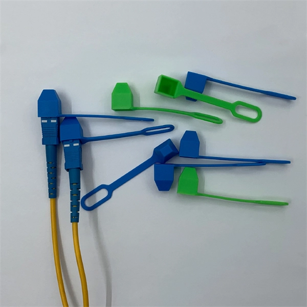
Align the fiber with the connector's guide. Ensure the fiber does not bend or twist during insertion. A proper fit prevents signal loss and enhances performance. Secure the connection using the fast connector's. Optical fiber fast connectors, also known as cold connectors, are becoming increasingly popular due to their ease of use and quick installation. Unlike traditional fiber connectors that require epoxy and polishing, fast connectors use a mechanical splice to join the fibers. In this article, we will. At the heart of any robust fiber optic network lies a crucial process: Preparing a fiber cable for termination of a connector or splice. Two types of splices are used in fiber optic cabling one is Mechanical the other is Fusion. Whether you're installing a new network, expanding an existing one, or. Optic Fiber cleaving, and mechanical splicing through very simple processes in this short series of videos. Thank you for supporting us by viewing our content. Doubts and suggestions? Leave us you. more Audio tracks for some languages were automatically generated. The primary purpose of a fast connector is to ensure a stable and reliable link. Connecting a fiber optic cable to a connector is a precise task that requires careful attention to detail, as well as some specialized tools and equipment. These terminations must be of the right style, installed in a.
[PDF]
The Telecoms crash, also known as the Telecommunications Bubble was a that occurred in 2001, after the bursting of the. The telecommunications industry had experienced significant growth and investment during the 1990s, fueled by the expansion of the internet and the introduction of wireless technology. Companies such as,, and had achieved enormous market valuations base.
[PDF]

This article will give you an overview of the use cases for fiber-optic networking, some of the terms used in fiber networking, and suggestions for setting up a fiber network. Once you understand the basic concepts, you can check out my Recommended Equipment section toward. Fiber tapping is a network tap method that extracts signal from an optical fiber without breaking the connection. Tapping of optical fiber entails diverting some of the signal being transmitted in the core of the fiber into another fiber or a detector. Fiber to the home (FTTH) systems use beam. Optical fiber is a technology used to transmit data by sending short light pulses along a long fiber, which is typically made of glass or plastic. In optical fiber communication, metal wires are preferred for transmission because the signals travel more safely. Optical fibers are also resistant to. Photo: Light pipe: fiber optics means sending light beams down thin strands of plastic or glass by making them bounce repeatedly off the walls. This is a simulated image. Note that in some countries, including the UK, fiber optics is spelled "fibre optics. " If you're looking for information online. This manual covers everything about fiber optic cables, how they work, where they are used, and what is new in this area of technology. The choice of fiber optic cable depends on the specific needs of the application, as well as the.
[PDF]

The fibers within a butterfly cable are housed in a tight buffer, reducing their exposure to tension and ensuring that any strain applied to the outer jacket does not translate directly to the optical fibers. The invention provides a flexible physical flame-retardant low-friction compression-resistant butterfly-shaped optical cable and a production method thereof, and relates to the field of optical cables. The optical fiber core is located in the center of the cable body, two reinforcing cores are placed on both sides, and the outer layer is enveloped and sheathed to form a cable. FTTH (Fiber to the. Fiber optic technology has revolutionized internet connectivity, and the Butterfly Fiber Optic Cable GDX702 stands at the forefront of this innovation. As fiber optic cable manufacturers continue to refine their products, understanding the technical intricacies becomes crucial for network planners. FTTH butterfly optic cables are specially engineered to facilitate high-speed internet connections directly to residential homes. Their name stems from the distinctive "butterfly" shape, which is a result of their layered construction. Its innovative design positions the communication unit at the core, flanked by two parallel non-metallic strength members (FRP) for enhanced compression resistance and.
[PDF]

This video goes over common types of connectors, their respective adapters, and how to properly connect and disconnect them. For your safety, it is always advised to follow proper fiber optic handling techniques and utilize the correct protective gear when performing. Plan your outdoor fiber installation carefully by surveying the site, choosing the right cable type, and following FOA and OSP standards to ensure reliability. Select the best installation method—direct burial, aerial, conduit, or underwater—based on your environment and future network needs. Use. Proper connection of fiber optic cables is essential to harness these benefits fully, as even minor errors can lead to significant performance issues like signal loss. more Are you interested in seeing how fiber optic connectors get. The Fiber Optic Association, Inc. (FOA) was founded in 1995 to help develop the workforce to build the fiber optic networks to support a rapid expansion in communications and the Internet. The charter of the FOA was to promote professionalism in fiber optics through education, certification, and. Outdoor OPT Fiber Optic connectors integrate common fiber interfaces (SC, duplex LC, MPO) inside a sealed, rugged housing for harsh environments. Each assembly houses a standard indoor connector (SC, LC, or MPO) within a waterproof shell. At its core, the optical fibers are enclosed within protective layers that are resistant to pressure, water, and ultraviolet radiation.
[PDF]
A simple rule is that each device needs two cores—one for sending and one for receiving data. Start by counting how many devices you're connecting. For example, if you have 10 devices, you'll need at least 20 cores. The total number of cores for a 1pc fiber patch cable is calculated as the number of branches multiplied by the number of cores per branch (if there are no branches, the number of branches = 1). For example, the total number of cores in an MTP®-8 trunk cable equals 4 (number of branches) x 8 (MTP-8. The number of optical cores in an optical fiber is the total number of equipment interfaces multiplied by 2, plus 10% to 20% of the spare quantity, and if the communication mode of the equipment has serial communication and equipment multiplexing, you can reduce the number of cores. The number of. One key factor is the number of cores, which impacts how much data you can transmit. This post will guide you through understanding fiber optic cores and selecting the perfect cable for your needs. Understanding Fiber Cores: Core: The central glass fiber that transmits light signals. For example, an MTP®-8 trunk cable with four branches and eight. Tip: Round counts to the connector pack before you buy. Tip: Keep one spare block for moves, adds, and changes. To calculate teh total number of fiber strands that will be.
[PDF]

Learn how to splice fiber optic cable using fusion splicing with this complete step-by-step guide. Includes tools, best practices, loss standards (ITU-T G. 652), cost analysis, and FAQs for network engineers and installers. Splicing fiber optic cable is an extremely important phase for making dependable, high-speed communication infrastructures. Regardless of the type of fiber network you're deploying, be it for telecom, enterprise data centers, or smart city infrastructure, fusion splicing provides the benefits of. This is where fiber optic cable splicing—the process of creating a permanent, high-performance join between two fiber ends—becomes critical. For network managers and technicians, a poor splice can lead to significant signal degradation, network downtime, and costly troubleshooting. At Turn-Key. Think of a fiber optic cable splice as the seamless stitching that keeps data flowing through the delicate threads of a network—like a master tailor joining fabric with precision. What is Fiber Optic Splicing and Why is it Needed? – #1. Discover how to efficiently use sleeves and the heat. The answer lies in splicing, both fusion and mechanical. In this comprehensive guide, we will delve into when.
[PDF]

