
Comprehensive Guide to Civil Construction for Telecom Tower Sites In the ever-evolving landscape of telecommunications, the construction of tower sites serves as the backbone for reliable network connectivity. A communication tower foundation design is the structural blueprint that determines the anchor point of the tower on the ground. This article delves into the intricate process of civil construction tailored. Telecom (Telecommunications) towers are a generic description of radio masts and towers built primarily to hold telecommunications antennas. As such antennas often have a large area and must be precisely pointed out, such towers have to be designed and built to limit wind induced movement. So very. With excellent resistance to axial and lateral loads in both compression and tension, they're an efficient and durable foundation that's easy to remove and remediate. Monopole towers are popular in urban areas owing to their minimal footprint and adherence to city planning. The foundation type can be either mat foundation or monopile foundation. If you're planning a new installation, knowing the basics of these foundations can help you establish a secure and durable tower that will be a community asset for years to come.
[PDF]
New relay installations require startup and commissioning to ensure proper protection for your system. Our experience in advanced utility and industrial relay applications includes: 1. General inspection of eq.
[PDF]
This article provides a comprehensive overview of the development of the energy Internet, including its architecture, several kinds of ERs, and the advantages and disadvantages of implementing it. There are several potential benefits that could result from this, such as: The Internet of Energy (IoE) can assist in locating and removing. Energy Internet is a concept proposed to harness, control, and manage energy resources effectively, with the help of information and communication technology. It improves a reliability of the system, and provides an increased utilization of energy resources by integrating the smart grid with the. Extensive electrification based on renewable energy sources is seen as one of the most potential growth options to tackle these issues in the medium to long term. The future of energy essentially requires novel thinking and new systems to transform energy generation, distribution, and consumption. The internet is a worldwide array of servers and.
[PDF]

Free electrical load calculation tool for residential and commercial buildings. Calculate service entrance sizing, panel loads, demand factors, and ensure NEC Article 220 compliance. Always verify calculations with a. Electrical load calculation is a critical process in electrical design that determines the total electrical demand of a building or facility. Proper load calculations ensure that electrical systems are safely designed with adequate capacity for present and future needs. What is Electrical Load. What is Electrical Load Calculation? 1. Connected Load (CL) 2. Demand Factor (DF) 3. It accounts. This technical drawing presents a detailed residential electrical service cabinet and main power distribution layout with accurate load calculations. The image shows meter installation, service cabinet arrangement, MCCB panel board, isolator positioning, and incoming and outgoing cable connections. This standard only addresses fixed (or. Electrical load calculator estimates power demand, ampacity, and panel capacity, guiding circuit sizing, load balancing, voltage drop checks, and NEC-compliant design for residential, commercial, and industrial electrical projects, planning safely.
[PDF]

This paper presents a set of newly developed modeling, simulation and testing tools aimed at better understanding the design concept and related applications for protective relaying and substation automation solutions for the smart grid. presentation of protection and control relaying. The report will identify methodology behind these practices, present issues raised by the integration of microprocessor relays and the internal logic and external communication configurations, ying. At Keentel Engineering, we specialize in modeling, simulating, and deploying advanced protective relays to ensure the robustness of medium-voltage (MV) and high-voltage (HV) networks. Our engineering services help utilities, OEMs, and renewable developers simulate real-world contingencies and. This Modern Power System Protective Relaying training course has been designed to provide a clear and perfect understanding of power system protection schemes and devices, including protection relays, fuses, circuit breakers, and other protective devices. In modern power systems, nowadays. To ensure that protective relays, circuit breakers, and other protection devices correctly and selectively isolate faults, minimizing damage to equipment and interruptions to customers while maintaining system stability. One-line diagrams and detailed network data (lines, transformers, buses).
[PDF]

We determine the noise coefficients of a Fiber Bragg Grating Accelerometer (FBGA) at static operation using Allan Variance Method. We describe the mechanical structure of the FBGA, as well as the embedded optical and electronic circuits used to acquire the experimental data. Fiber Bragg grating (FBG) sensors have emerged as advanced tools for monitoring a wide range of physical parameters in various fields, including structural health, aerospace, biochemical, and environmental applications. This content is available for download via your institution's subscription. To access this item, please sign in to your. Abstract – Fiber optic Bragg gratings have found increasing applications to seismic strain measurement of underground structures and rock mass. The strain sensitivity of a Bragg grating measuring system, however, is limited by the noise caused by the instability of the laser wavelength and the. Fiber Bragg grating (FBG) sensors have proven to be adaptable for monitoring various physical quantitites like temperature, strain, or even vibrations and acoustic noise. Several interrogation methods, like spectroscopic evaluation, interferometric interrogation, active scanning or active filtering.
[PDF]
This specialized hook allows operators to remotely engage and disengage electrical connectors, reducing the risk of accidental contact with energized components. A plug-and-play safety system for industrial machinery that provides an ANSI-compliant emergency stop, accidental restart protection, and motor control. This one device provides three distinct safety features that help to prevent injuries and avoid OSHA citations. These features are: This standard. Search the exact automotive plug, pigtail, or OEM connector you need in 30 seconds or less. No confusion, no part hunting, just results. Repair-first mindset, replace the connector, fix faster, skip full harness replacements. Built for techs, trusted by shops, wiring parts shouldn't slow you down.
[PDF]
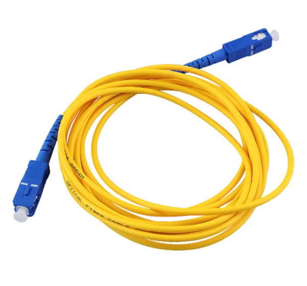
Directory of 84 fiber optic cable manufacturers in the US. Find fiber optic cable assemblies, connectivity products, and subsea cables, plus contact info and. Buyers seek manufacturers to solve challenges like achieving specific optical return loss (ORL) targets for. Thomas has been North America's number one industrial sourcing platform for more than 125 years. You can filter these companies by location, certifications, and more factors to easily find and connect with the right. 171 Fiber Optic Cable manufacturers listed. Fiber optic cable is composed of two layers of glass, the core, which carries the actual light signal, and the cladding, which is a layer of a glass surrounding the core. Narrow down on the. Find 1,029 Fiber Optic Cables suppliers with GlobalSpec. Our catalog includes 106,451 manufacturers, 20,792 distributors and 94,628 service providers. Charlton Precision. The data fields provide comprehensive information including a description of the Fiber Optical Cable product, its HSN code, shipment date, price, quantity, countries of origin and destination, ports of origin/destination, details of Suppliers and Buyers, and top decision makers' contact.
[PDF]
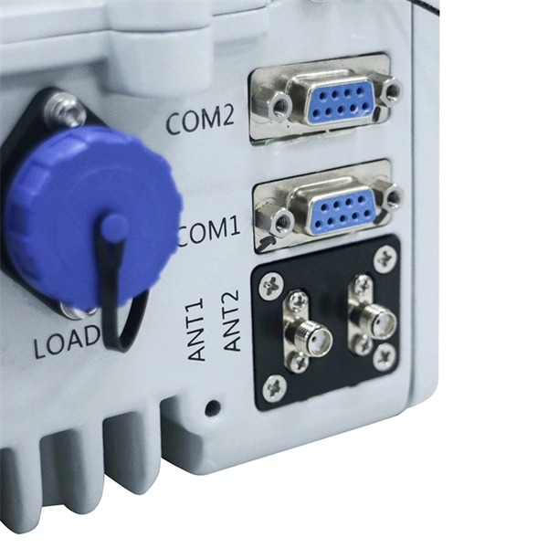
It refers to the function that allows network operators to access real-time operational information from optical transceivers. This includes key parameters like temperature, supply voltage, laser bias current, and transmit/receive optical power. This document defines an enhanced Digital Diagnostic Monitoring Interface (DDMI) available in Finisar SFP and SFP+ optical transceivers. ) The interface allows real time access to device operating parameters, and it includes a system. DDM stands for Digital Diagnostic Monitoring (also called Digital Optical Monitoring, or DOM). Defined under the SFF-8472 Multi-Source Agreement (MSA), DDMI ensures compatibility across devices from various manufacturers. By providing real-time data on the state of. This specification is made available for public review at https://www. org/sff/specifications. Comments may be submitted at https://www. Comments received will be considered for inclusion in future revisions of this specification. The. Soft Flags (bits on address 0xA2, byte 110) ofer a mirror of the hard pin state warnings (e. TX Disable, RX SD) accessible via the two-wire serial interface. Related Articles: What is DDMI? How to use DDM information effectively SFF-8636 is an MSA standard that defines.
[PDF]

The formula used to calculate cable tray capacity is: Cable Tray Capacity = (Tray Width × Tray Depth × Fill Ratio) / Cable Cross-sectional Area Where: Tray Width is the internal width of the cable tray in meters (or millimeters). Using our advanced cable tray load calculator is simple and ensures your electrical installation meets structural and safety standards. Follow these steps to generate your accurate Bill of Materials (BOM) and engineering report: Step 1: Define System Specifications: Select your cable tray type. Wire Mesh Cable Tray Fill Ratio = Cross section of cable / Cross section of tray According to NEC 392. 9 (B), when using ventilated tray with multi conductor control cable, the sum of the cross sectional areas shall not exceed 50 percent of the interior cross section of the cable raceway / tray. We independently provide precision steel tools, calculators, and expert resources for steel, metalworking, construction, and industrial projects. I'm here to tell you, it's simpler than you might think, and it makes a huge difference. This guide will walk you through how to work out those loads. An overloaded cable tray can lead to structural failure, causing damage to cables and potentially resulting in costly downtime and safety hazards. Divide this by the cross-sectional area of a single cable to find the.
[PDF]


