
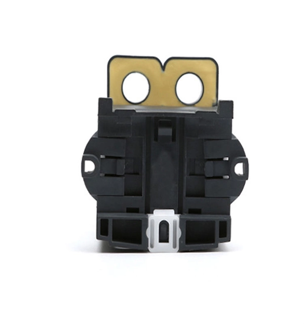
Busbars operate as conductive bars that distribute electricity from incoming feeders to outgoing circuits within an electrical system. By providing a low-resistance path, busbars ensure efficient current distribution with minimal power loss. These components are typically mounted within an. Electrical busbars are solid conductors used to carry and distribute high current in switchgear, panels, substations, and power systems. This guide explains how busbars work, common types, key design factors, and how to choose the right busbar for your application. An electrical busbar is a solid. The busbar electrical system performs several essential functions that support efficient power management: Power Distribution: It is a central station to which the electrical power is brought out of one source and to more than one circuit. Existing Transmission: Electric busbar transmits huge. I. Basic Definition of the Small Busbar at the Top of the High-Voltage Cabinet The small busbar at the top of the high-voltage cabinet, as the name suggests, is a small busbar device installed at the top of the high-voltage switchgear. Its primary role is to carry large current loads and connect multiple circuits together. Think. An electrical busbar functions as a metallic conductor, playing a pivotal role as a central link for multiple electrical connections. These connectors can take on various forms including solid, hollow, or even flexible designs to suit different needs.
[PDF]

The PE/PEN combination, comprising busbars, combination angles and baying brackets, supports type-tested configurations to IEC 61 439-1. For assembling 1-pole neutral or PEN conductors. Self-holding nut with knurled ring. Discover the robust selection of secondary pedestals at Hubbell, designed to enhance and secure your power distribution needs. These secondary pedestals are built to withstand harsh environments, ensuring long-lasting reliability and performance. Ideal for a variety of utility applications, they. These bars are tin-plated copper and have stainless steel terminals. Also known as bus bars, they serve as connection points between wires with ring or spade terminals. The underside is sealed, so the bars can be safely mounted to conductive surfaces. Distribution Bar Covers— Distribution bar. Busbars (bus bars) are integral to power distribution and serve numerous industries including automotive, industrial, and aerospace. Busbars are metal bars that can be composed of numerous alloys but are most commonly copper or aluminum. Typical busbar applications include switchgear, panel boards. For attaching the PE/PEN busbar 30 x 5, 30 x 10, 40 x 10 and 80 x 10 mm. With SIRIUS, SENTRON, SIVACON and ALPHA, we offer an innovative portfolio for standard-compliant and demand-oriented applications. Power Busbar System is a modular energy transmission and distribution system created by insulating current carrier Aluminium or Copper busbar conductors placed in a closed body.
[PDF]

The Cable Tray Sizing Calculator is an electrical calculator tool designed to determine the correct cable tray dimensions for electrical installations. Accurate fill ratio analysis and tray sizing per NEC, IEC 60364, and BS 7671 standards. Follow these simple steps: Define Tray Dimensions: Enter the width and depth of your planned cable tray (in mm or inches). Select Fill Standard: Choose 40% for power cables (NEC compliant) or 50% for. The all-in-one desktop software for cable tray sizing, fill rate analysis, bracket design, seismic verification, and thermal expansion calculations. Fully compliant with IEC, BS, NEC, VDE, and AREI standards. cable tray engineering. From initial sizing to final documentation — one tool handles it. Calculate cable tray fill ratio, weight loading, and derating factors for multi-standard compliance. This calculator features an interactive interface with advanced visualizations. Open the full calculator for the best experience. 0133 sq in each, the screen is about 0. This page is a preliminary cable-tray occupancy screen for early layout work. You need to install 50 power cables, each with a diameter of 0. The calculator would help determine if the chosen tray is sufficient or if a larger size is. Determine the total usable cross-sectional area of the cable tray by multiplying its width by its height (or depth). For mixed cables, sum the areas of all individual cables.
[PDF]

This paper describes a reliable substation protection system that involves busbar protection, station-wide breaker failure protection, and advanced zone selection. IV EXECUTIVE. GE Multilin provides protective relays that support all busbar protection techniques, including overcurrent, high-impedance differential, and percentage (low-impedance) differential. GE Multilin. Modern numerical relays use innovative algorithms to fulfill busbar protection requirements of fast operating times for all busbar faults, security for external faults with heavy CT saturation, and minimum delay for evolving faults. Busbar protection is critical for the safe and reliable operation of a power system. Related Article: Busbar Protection Like any other faults. As a professional transformer and switchgear manufacturer, Hangbian Power Technology Co. provides customers with a complete set of power equipment solutions, including high- Voltage Switchgear, low-voltage distribution cabinets, box type substations, etc. The core value of the busbar. A busbar protection is a protection to protect busbars at short-circuits and earth-faults. In the “childhood” of electricity no separate protection was used for the busbars. With increasing short-circuit power in the network.
[PDF]

Mechanical Optical Switches: Switching times typically range from 1-10ms, suitable for long-distance transmission scenarios where latency is not critical (such as backbone network protection switching). Solid-State Optical Switches: Based on thermooptic or electrooptic effects, response. We lead the industry in optical switch technology, delivering the lowest insertion loss (0. 2 dB), fastest switching speed (10 ns), broadest wavelength range (300–2400 nm), widest fiber compatibility, highest optical power handling (50 W), and space-qualified reliability. Backed by over 25 years of. Use this optical switches buying guide to compare major types, define selection criteria, and find suppliers: Professional purchasing of high-value photonics products is a substantial responsibility, where a structured decision-making process is essential. RP Photonics offers a lot of help: Get. This document is a troubleshooting and selection guide for common optical switch failures, compiled based on over 500 field cases. These switches are built on proven, reliable optomechanical technology that has seen more than 30 years of successful operation. Each. The POLATIS ® Series 7000 384x384 all-optical circuit switch is designed to meet the most demanding applications with exceptionally low optical loss, compact size, and fast switching speeds. With support for Software-Defined Networks (SDNs) via embedded NETCONF and RESTCONF control interfaces, the.
[PDF]

Free electrical load calculation tool for residential and commercial buildings. Calculate service entrance sizing, panel loads, demand factors, and ensure NEC Article 220 compliance. Always verify calculations with a. Electrical load calculation is a critical process in electrical design that determines the total electrical demand of a building or facility. Proper load calculations ensure that electrical systems are safely designed with adequate capacity for present and future needs. What is Electrical Load. What is Electrical Load Calculation? 1. Connected Load (CL) 2. Demand Factor (DF) 3. It accounts. This technical drawing presents a detailed residential electrical service cabinet and main power distribution layout with accurate load calculations. The image shows meter installation, service cabinet arrangement, MCCB panel board, isolator positioning, and incoming and outgoing cable connections. This standard only addresses fixed (or. Electrical load calculator estimates power demand, ampacity, and panel capacity, guiding circuit sizing, load balancing, voltage drop checks, and NEC-compliant design for residential, commercial, and industrial electrical projects, planning safely.
[PDF]
Enter the dimensions of the cable tray, the desired fill ratio, and the diameter of the cables to calculate the cable tray capacity. This calculator helps determine the maximum number of cables that can be laid in a cable tray while adhering to the specified fill ratio. Follow these simple steps: Define Tray Dimensions: Enter the width and depth of your planned cable tray (in mm or inches). Select Fill Standard: Choose 40% for power cables (NEC compliant) or 50% for. A Cable Tray Capacity Calculator is an essential tool for electrical engineers, contractors, and project managers involved in the installation and management of electrical cables. Determine whether cables fit within safe fill limits. Accurate fill ratio analysis and tray sizing per NEC, IEC 60364, and BS 7671 standards. Enter your cable schedule below to get started. IEC 61537 covers cable tray and cable ladder systems for the support and accommodation of cables, while NEC Article 392 governs cable.
[PDF]

In this paper, various operational factors affecting 100G transmission over G. D fiber-cables are discussed to make the right fiber selection for the long-haul network. Selecting appropriate G. 652 fibre was originally optimized for use in the 1310 nm wavelength region but can also be used in the 1550 nm region. This is the latest revision of a Recommendation that was first created in 1984 and deals with some relatively minor modifications. a number of concatenated cable. G. 92% of. Fiber optic cables are the ultimate technology used in data transfer using light waves. They are classified based on wavelength band, core/cladding size, application, and compliance with international standards such as IEC, ITU-T, and TIE/EIA. In the next sections, the real artwork is putting on. This guide explains the most important ITU-T G. 655—to help you make an informed decision for your project, whether it's a long-haul backbone or a final FTTH drop. In the world of fiber optics, not all glass is created equal. The core of every cable—the optical. Because GPON and XGS-PON are deployed in diverse environments, fiber-containing components such as PLC splitters must be evaluated not only by their standard parameters but also by their sensitivity to bending loss, which is critical for maintaining stable optical transmission. The ITU-T defines.
[PDF]

This document discusses the implementation for Cisco Software-Defined Access (SD-Access) deployments for Airports. For the associated deployment guides, design guides, and white papers, refer to the following documents:. The low noise Silent Switcher architecture simplifies design and PCB layout to help streamline development and reduce the chance of a redesign. The compact Silent Switcher solution size supports a range of applications, including industrial, instrumentation and measurement, healthcare, aerospace. AIRPORT ELECTRICAL DESIGN STANDARDS Los Angeles World Airports 1. 1 GOALS The goal of this section is to provide guidance for all electrical work at LAWA. Additional discipline specific guidance related to electrical work can be found throughout the Design & Construction Handbook (DCH). This page provides a quick reference to engineering, design, and construction standards for various airport-related equipment, facilities, and structures. Visit our Series 150 Advisory Circular Library for a complete listing of current advisory circulars. Simpleway's battle-tested hardware ecosystem combines nnounce audio devices with digital signage controllers, creating a unified communication infrastructure built from real airport experience - from routine gate operations to full-terminal evacuations. Discover how nnounce devices create a.
[PDF]

This guide covers everything: what fiber optic pigtails are, how they differ from patch cords, which connector and polish type to specify, how to choose between mechanical and fusion splicing, and the real-world applications where pigtails are the right call. In this guide, we cover the basics of fiber optic splicing, how to perform splicing using two different methods, and finally some best practices to perform good fiber splicing. What is Fiber Optic Splicing and Why is it Needed? – #1. Whether you're building out an ODF. Think of a fiber optic cable splice as the seamless stitching that keeps data flowing through the delicate threads of a network—like a master tailor joining fabric with precision. Whether repairing a broken cable or extending a fiber run, fiber optic splicing ensures light signals travel. Fibre optic splicing is an essential skill in the world of modern telecommunications, offering a reliable method to connect optical fibres for seamless data transmission. As the demand for high-speed internet and robust communication networks continues to grow, learning to splice fibre optics is. In this guide, you will find a chronological description of the fusion splicing process, the principal technical standards, and answers to the real-life questions network engineers and procurement teams may have. Therefore, we will also touch on cost factors, risk management, and best practices in.
[PDF]
The aluminium alloy joint box are applicable for connection protection of special optical cables,with the functions of direct and branch connection, with the maximum of 6 optical cables, which mainly for overhead rods and towers. Explore top-quality OPGW hardware fittings, setting a new standard for secure and efficient connections in our Pole Line Hardware. The joint box is made of aluminium alloy and has a maximum capacity of 192 fibre splices. A pre-moulded neoprene anti-aging gasket. No. 77, East District, Sixian Industrial Zone, West Ring Road Office, Renqiu City,. An assembling plate trays is placed inside the box. Cable glands and a heavy wall OPGW cables. The anchoring of the joint box to the tower is poles. It features in high mechanical strength, good airtight and anti-corrosive. Having been sealed with sealing ring and silicone, it could be opened, expansed, fixed, and connected repeatedly. It's suitable in aerial. Optical cable junction boxes play a crucial role in connecting and protecting optical fibers, directly influencing the quality and lifespan of optical cable routes. Optical cable splice boxes protect the splicing parts of optical fibers from various hazards, such as water seepage due to adverse.
[PDF]

Compare fiber optic and copper Ethernet cables across speed, distance, cost, installation difficulty, and use case metrics. Use the interactive scenario selector to find the right medium for your specific network — all processed locally in your browser. PoE Required?. The core difference between fiber optic and copper cables lies in how they carry data. One uses light, the other electricity—and that distinction shapes everything from speed to signal integrity. Fiber optics transmit data as pulses of light through ultra-thin strands of glass or silica. Both technologies can deliver high-speed connectivity, but they behave differently under real-world constraints such as. However, the exponential growth in data demand has positioned fiber optic technology as the superior alternative for performance, scalability, and future-readiness. This article provides a detailed technical comparison between fiber optic and copper cables, offering a clear perspective for. Fiber optic tends to be the more premium solution, while copper wiring is far more common, but why is that? What are the differences between these two cable types, and why might you want to pick one over the other? Here's everything you need to know about fiber vs. copper cables, to help you pick. Several factors are converging to drive the switch from copper to fiber – and cost is a big one. A recent investor presentation by AT&T claimed that fiber was 35% less costly to maintain than copper.
[PDF]

This report provides a comprehensive 2026 analysis and a forward-looking forecast to 2035, dissecting the complex interplay between burgeoning solar capacity targets, evolving supply chain dynamics, and intense competitive pressures. A busbar is an essential component in any electrical busbar system, designed to distribute power efficiently and safely across electrical circuits. Found in electrical panels ranging from residential buildings to heavy industrial facilities, busbars simplify complex wiring systems and ensure stable. Source: Secondary Research, Interviews with Experts, MarketsandMarkets Analysis The busbar market is projected to reach USD 27. 71 billion by 2035 from USD 15. 8% from 2025 to 2035. There is an increasing need for busbars due to industrialization, strict government. The Bus Bar Price is included in our comprehensive Busbar range. Consider factors like conductivity, weight, and corrosion resistance. Use a material guide to select the top choices suited for your applications. The Asia Pacific Busbar Market Size is expected to have 4. The Asia Pacific busbar market refers to the production. The ASEAN market for copper ribbons and busbars for photovoltaic (PV) applications stands at a critical inflection point, shaped by the region's accelerating energy transition and its strategic position in global solar manufacturing. This report provides a comprehensive 2026 analysis and a.
[PDF]
