
A distribution box, also known as a junction box or distribution point, is a enclosure or housing used to distribute electrical or telecommunications cables to multiple directions. A distribution box (DB box) is a key part of electrical wiring, acting as a central hub where cables branch out to various outlets and switches in a building. It supports different cable sizes and types, enabling smooth and fast power distribution. Each. Distribution boxes, also known as electrical distribution boards or panels, are pivotal components in electrical systems, ensuring the safe and organized distribution of electrical power throughout residential, commercial, and industrial environments. These boxes house various circuit breakers. With the new distribution box, centrally routed cables can be distributed 360° in all desired directions. Cables with and without connectors can be routed, sealed with IP54 (acc. to 60529) and strain relieved in accordance with EN 62444. This article will provide a detailed introduction to electrical distribution boxes, including their functions, components, types, and uses. Today, electrical systems are essential for homes and industries. But what exactly is a power distribution box, and why is it so essential in our daily lives? The DB panel board controls the flow of electricity.
[PDF]

Fiber optic terminal boxes provide functions such as input, branching and splicing of optical fiber cables. Through the connectors and splicing boxes in the terminal box, optical fibers can be quickly connected and repaired. Serving as a critical connection point, FTB facilitates the termination, splicing, or connection of fibers from various cables to other network devices such as switches, routers, or Optical Network Terminals (ONTs). It aids in splicing, splitting, storing, and managing fibers within the appropriate. The optical fiber terminal box is the terminal joint of an optical cable, one end of which is an optical cable, and the other end is a pigtail, which is equivalent to a device that splits an optical cable into a single optical fiber. A fiber pigtail is a specific hardware connection used for cable termination. It is a small enclosure that can house and protect the fiber optic cables, splices, and connectors. The optical fiber termination box and optical fiber splice box serve distinct purposes and are not interchangeable.
[PDF]

from outside the US. EMEA Specific: +49 (0) 228 7489 201 HCS and GiHCS are registered tradema time without notice. This document is for informational purposes only and is not intended to modify or supplement any OFS warranties or specifications relating to any of its. from outside the US. STFOC uses our patented cable jacket construction designed to protect the fiber in the harsh subsea environment. Non-KinkTMSTFOC has a patented design to protect. CommScope bundles hybrid cabling to your custom specifications, using our high-performance fiber-optic, unshielded twisted pair and coaxial cables. Devices deployed at the network edge—a 5G radio, a security camera, or an industrial sensor—require high-speed data connectivity and power. It is technically possible to have a separate fiber and electrical cable, but it adds complexity, cost, and maintenance overhead. Optical hybrid cables address. challenge—OCC has what you need. Our team will make sure the configuration is tailored to your needs and will provide a detailed quote. Email us using the Request a Quote below, or give our team a call. Drive, Avon, CT 0600 erat ing Bend Radiu erat ing Bend Radius Cons from outside the US. Teledyne ODI ofers a comprehensive line of fiber optic and electro/optic hybrid wet mate interconnect products. Wet mate connectors are available in ROV Mate, Stab Mate and Manual Mate configurati sm.
[PDF]

In telecommunications, a base station is a fixed transceiver that is the main communication point for one or more wireless mobile client devices. It further connects the device to other. A communication base station is composed of a computer room, base station, antenna, feeder line (transmission line between transmitter and antenna), and supporting equipment. The antenna is at the top of the signal tower, and below the tower is a computer room. Along with increased capacity demands driven by the explosion of cloud and connected device growth, engineers need interconnects that enhance the design. A base transceiver station (BTS) or a baseband unit (BBU) is a piece of equipment that facilitates wireless communication between user equipment (UE) and a network. UEs are devices like mobile phones (handsets), WLL phones, computers with wireless Internet connectivity, or antennas mounted on. Fiber Optic Cables: High-speed fiber optic cables connect the BBU to the RRUs (RE part). Signal Transmission: The optical signals carry data, control, management, and synchronization information. Topology: The BBU and multiple radio heads can be connected in cascade or star configurations. The rise. The design investigates the possibilities of Free-Space Optical (FSO) communication systems and MilliMeter-Wave (MMW) technologies operating at 60. Although these technologies are highly effective and have a high throughput, they are nevertheless vulnerable to weather phenomena like rain.
[PDF]

Urban Areas: 25–40m spacing (concrete poles, 10–12m height)., steel lattice structures). Factors: Cable weight (kg/km) Ice loading (up to 50mm. The Fiber Optic Association, Inc. (FOA) was founded in 1995 to help develop the workforce to build the fiber optic networks to support a rapid expansion in communications and the Internet. The charter of the FOA was to promote professionalism in fiber optics through education, certification, and. to n utral comm. cable R. FO-CS JOINT USE CLIMBING SPACE REQUIREMENTS 51. APPENDIX A - COVER SHEET / TOC 52. RUS DRAWING #PM12 58. CHECK. d suppliers of electrical construction services. They define a minimum baseline of quality and workmanshi for installing electrical products and systems. NEIS® are intended to be referenced in contrac documents for electrical construction ation or liability to users of this publication. Choose the type of pole The basic pole height is 7m and the tip diameter is 150mm. In case of special sections, crossing obstacles or roads or railways, the pole height of 8m, 9m, etc. can be selected. Cables 300 V or less need to be a minimum two feet over the street light. Climbing Space is an unobstructed, vertical space along the side or corner of the pole. In gen-eral, it consists of an imaginary box, 30-inches square, extending at least 40 inches above the highest communications cable or.
[PDF]

The two primary industry-accepted methods for fiber optic cable splicing are fusion splicing and mechanical splicing. The choice between them depends on performance requirements, budget constraints, and the specific application environment. To begin, the standard definition of splicing in optical fiber is joining two fiber optic cables together. Splicing is most commonly used in the field but has application in cable assembly houses. Infield. In this guide, we cover the basics of fiber optic splicing, how to perform splicing using two different methods, and finally some best practices to perform good fiber splicing. What is Fiber Optic Splicing and Why is it Needed? – #1. In this guide, we'll explore what splicing of fiber entails, why it's important, and dive into the key methods and tools. So in essence, fiber optic splicing is a process used to join two separate fiber optic cables together. Through splicing, fiber optic technicians can extend the length of the fiber to make it long enough for use in a required cable run. As. Splicing fiber optic cable is an extremely important phase for making dependable, high-speed communication infrastructures. Termination is the other, more frequent way of linking fibers. Fiber splicing is the preferred way when cable lines are too long for a single length of fiber or when combining two different types of cable.
[PDF]

Will fiber optic cables replace coaxial cables entirely? The short answer is: not entirely. In this article, we'll help you understand where each. Fiber optic cables and coaxial cables have something in common; both of them can provide homes and businesses with tv, phone, and Internet service. Cables. Optical fiber can carry analog RF signals from antenna to receiver with far less loss than coaxial cables. It's not unusual in engineering to find solutions to long-standing problems leveraging apparently unrelated technologies. But these signals have a fatal flaw: when transmitted through traditional copper coaxial cables, they degrade and distort rapidly over distance. It's like shouting into a long metal pipe—the sound that comes out the other. Seamless Radio Frequency Signal Transmission over Optical Networks RF over Fiber (RFoF) technology enables the transmission of radio frequency (RF) signals over optical fiber instead of traditional coaxial cables. This method combines the advantages of fiber optics—such as low signal attenuation.
[PDF]

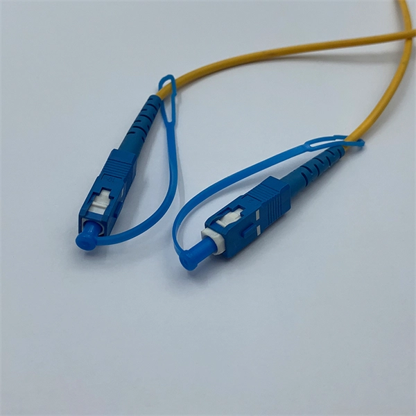
Mainly 9steps: Step 1: cut cable with cutting machines in lengths Step 2: put the connector spare parts on the cable Step 3: Strip cable jacket, coating till bare fiber, and make all parts in ready Step 4: Insert fiber into ferrule, glue dispenser and heat oven Step 5:. Mainly 9steps: Step 1: cut cable with cutting machines in lengths Step 2: put the connector spare parts on the cable Step 3: Strip cable jacket, coating till bare fiber, and make all parts in ready Step 4: Insert fiber into ferrule, glue dispenser and heat oven Step 5:. Learn how to make a fiber optic patch cord step by step, from preparation to testing, for reliable high-performance connections. Most guides on making fiber optic patch cord 1 s feel incomplete. They often focus on the final assembly steps, leaving the foundational stages a mystery. From cable cutting to connector assembly and testing, you will gain valuable insights into the production of. Fiber optic patch cords and Pigtails are very important passive fiber optic components in fiber optic networks. Use the fiber optic cleaver to cut the. This document describes the installation and use of the mode-conditioning patch cords listed in Table 1. A mode-conditioning patch cord is shown in Figure 1 IEEE 802. 3z-compliant optical fiber assembly consisting of a single-mode fiber permanently coupled off-center to a 62. 5-micron multimode.
[PDF]
There are hybrid optical and electrical cables that are used in wireless outdoor Fiber To The Antenna (FTTA) applications. In these cables, the optical fibers carry information, and the electrical conductors are used to transmit power. These cables can be placed in several environments to serve antennas mounted on poles, towers, and other structures. According to Telcordia GR-3173, Gener. OverviewA fiber-optic cable, also known as an optical-fiber cable, is an assembly similar to an but containing one or more that are used to carry light. The optical fiber elements are typically individually. Optical fiber consists of a and a layer, selected for due to the difference in the between the two. In practical fibers, the cladding is usually coated wit. In September 2012, NTT Japan demonstrated a single fiber cable that was able to transfer 1 per second (10 bits/s) over a distance of 50 kilometers. Although larger cables are available, the highest stra.
[PDF]
Unlike traditional metal-style reels, MARS is a lightweight, modular system constructed of an impact modified polymer that is easily transported. It is ideal for applications where cable needs to be deployed and reeled in quickly and stored efficiently. OCC's Modular Advanced Reel System (MARS ®), the industry's first lightweight cable deployment reel system, is designed specifically for the demanding needs of harsh-environment fiber optic installations. The dual take-ups are designed to work independently from line controls, therefore providing an easy adaptation and a fast plug & play installation to any line.
[PDF]
This article will guide you through the process of troubleshooting fiber optic connections, with a focus on ensuring proper TX and RX alignment and how to correctly switch patch cables to resolve issues. Proper connection of fiber optic cables is essential to harness these benefits fully, as even minor errors can lead to significant performance issues like signal loss. When issues like signal loss, slow speeds, or intermittent connectivity arise, systematic troubleshooting is key. This guide will walk you through diagnosing and resolving common. The process to connect fiber optic cable to router requires careful attention to detail, but I'll walk you through every critical step with the precision and clarity you deserve. This comprehensive guide combines industry standards with field-tested practices to ensure you achieve a rock-solid. Fiber optic cables are widely used in modern networks for their high-speed data transmission capabilities and resistance to electromagnetic interference. However, like any other networking technology, fiber optics can encounter issues that disrupt communication. One of the most common problems in. Fiber optic internet delivers blazing-fast speeds and reliable connectivity, making it a top choice for modern homes and businesses. Their ability to transfer large amounts of data at lightning speed makes them a go-to for efficient communication. Knowing how to avoid signal loss in.
[PDF]

Long Expansion Cycle: Optical fiber preform production has high technological barriers, and the expansion cycle can take as long as 18-24 months. Even if manufacturers start expanding immediately, the new capacity will not be available until at least 2027. This phenomenon is the result of multiple factors, including tight supply of optical fiber preforms (preforms), long expansion cycles for optical fiber production capacity, and the explosive growth of emerging applications such as AI computing power and drones. The expansion cycle of optical fibers is generally less than 6 months, and fiber optic cables can take 3 months. The expansion of production requires the purchase of equipment and the construction of factories. At the heart of this transformation lies fiber optic cable manufacturing, a precise and sophisticated process that powers our interconnected world. With the global fiber optic market reaching $6 billion and growing at 10% annually, the need for high-quality manufacturing solutions has never been. The manufacturing process of fiber optic cables involves several intricate steps that culminate in the production of high-performance data transmission solutions. This process begins with the creation of a preform, which serves as the foundation for the optical fibers within the cable. This intricate process combines cutting-edge technology, precise engineering, and.
[PDF]

This article will compare waterproof connectors and non-waterproof connectors, highlighting their key differences, advantages, and best use cases in FTTH deployments. 🔍 What Are Waterproof Connectors?. In modern fiber optic deployments, one of the biggest challenges is ensuring stable and long-term connectivity in harsh outdoor environments. The comparison is typically triggered during outdoor deployments, edge network extensions, or hybrid indoor–outdoor transitions where connectors may be exposed. This is where Ruggedized Fiber Optic Connectors come in. Whether you are connecting a Remote Radio Unit (RRU) for Ericsson, Nokia, or Huawei, or setting up a harsh-environment sensing network, choosing the right waterproof interface is critical to preventing signal loss and network downtime. In. In today's fast-paced digital world, the choice of fiber optic connectors can significantly impact performance, reliability, and longevity of networking solutions. Among the varieties available on the market, waterproof fiber optic connectors have emerged as a superior option for many applications. In this blog, we will focus on comparing the performance of Mini LC.
[PDF]

