
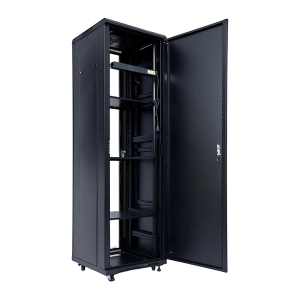
✅ 1U steel aluminum rack drawer. ✅ Pre-drilled for easy rack ing on standard 19” rack. 81”) deep steel chassis with aluminum front. ✅ Cooling side vents. 19 inch Horizontal Rack Mountable 1U PDU Available. 6-way and 8-Way Universal Socket 19″ Rack Mount PDU Power Distribution Units Available in Different Brands Like TOTEN, NEC, Matrix e. Also Available in Non-Branded (Chinese) Variants. 37"H. Shop your favourite Server Racks & Cabinets with us because we offer a price matching guarantee. If you find better pricing, share the screenshot or URL. We will match the price and even give you an additional discount. We guarantee 100% after-sale service, and all of our products come with a full. We have Wall mount and a free-standing Data cabinet from 4U - 42U. Market Forecast By Form Factor (1U, 2U, 4U), By Data Center Type (Mid-Sized, Enterprise, Large Data Centers), By Tier Type (Tier 1, Tier 2, Tier 3, Tier 4), By Services (Design and Consulting, Installation and Deployment, Support and Maintenance), By Industry (Banking, Financial Services and. A 1U rack mount server cabinet is a cabinet in which one or more servers can be placed in a rack. There are different types of 1U server cabinets, which include; Small Compact 1U Server Cabinets: These cabinets are ideal for.
[PDF]
Get gi cable trays in Dubai, Dubai at best price. A form of cable management system used for supporting and arranging electrical cables and wires in commercial, industrial, and residential structures is known as GI Cable Tray, also known as Galvanized Iron Cable Tray. It offers cables a secure and organized path, assisting in maintaining adequate. West Port Cable Tray is recognized as one of the leading manufacturers and cable tray suppliers in UAE, specializing in premium cable management systems within the Middle East. Our product range is meticulously designed to ensure durability, compliance with regulations, and operational efficiency. Galvanized cable tray with a size of 100mm x 50mm stands as a fundamental solution for efficient cable management in contemporary industrial and commercial settings. 4416/17, Phase-3 K- Road, GIDC Dared,, Survey No. - 127/02. Cable trays - large product range in ELMARK. GI Cable Tray 600mm x 50mm is a durable and reliable cable tray solution for industrial applications. It is designed to provide an efficient and safe way to route cables and wires.
[PDF]
Discover APAR Gigavolt hybrid power and fibre cables that cut rollout time, simplify cable management and lower TCO for 5G, IoT and DAS networks. CommScope bundles hybrid cabling to your custom specifications, using our high-performance fiber-optic, unshielded twisted pair and coaxial cables. Buy Direct From The Online Leader in 10-Gigabit Rated Copper and Optical Cables. We always maintain high stocking levels of the. DuetConnect Hybrid Copper-Fiber Cables allow one cable to offer the advantages of DC power and fiber, safely delivering both over long distances to remote locations where standard power is unavailable or too costly to install. These cables integrate fiber optics for high-speed data transfer and copper conductors for power delivery. American Tech Supply is a telecommunications based national stocking distributor of Hybrid Fiber Optic Cables, Hybrid Fiber Cables, Hybrid Singlemode Fiber Optic Cable, Hybrid Multimode Fiber Optic Cable,singlemode fiber optic cable and multimode fiber o ptic cables ranging from 2 fiber to 264 576. Juniper offers a broad portfolio of high-performance and cost-effective optical and electrical cables in various form factors and speeds for data center and campus networks. A wide selection of breakout configurations enables network operators to split out to lower speeds of Ethernet, increase port.
[PDF]
This cabling system organizes and manages fiber optic cables and copper cables through cable trays, patch panels, and structured cabling systems, enabling easy maintenance and scalability. Fiber and Cat6a can run together in shared trays when properly separated. Protect the fiber bend radius at all transition points. Avoid stacking heavy copper bundles on delicate fiber. Separate power cables from data cabling. Prevent tray overcrowding to maintain airflow. Wire mesh trays enhance. Data center cabling refers to the organized system of cables and related infrastructure to connect and manage the various components within a data center. This system ensures efficient data transmission and reliable connectivity in a data center environment. Structured cabling is a methodical. As data centers continue to grow in complexity and scale, efficient fiber optic cabling is essential for maintaining high performance, reliability, and scalability. Cabling not only supports current performance but also ensures future adaptability. Proper planning and implementation of cabling infrastructure can significantly reduce downtime, improve airflow, and ensure.
[PDF]

Filter your results below. The 400G OSFP SR8 optical module supports speeds up to 425Gbps, short-range distance reaching up to 100m over 16 parallel multimode fiber (MMF) OM4. OSFP-400G-SR8 has an MTP/MPO-16 connector. 400G SR8 is designed based on PAM4 (Pulse Amplitude Modulation 4-level) modulation technology, DSP (Digital. MaxLinear's highly integrated PAM4 DSPs offer superior link-margin performance and low power to enable 100G, 400G, 800G, and 1. 6T optical interconnects inside the data center. NADDOD OSFP-400G-SR4 optical transceiver is a four-channel, parallel, pluggable fiber-optic OSFP with built-in Broadcom DSP and Broadcom VCSEL, designed for 400G Ethernet applications. It integrates four transmit and four receive lanes, each operating at 53. 125 GBd, delivering an aggregate. Support 100GBASE per lane in multimode fiber. Fibres: 8 fibres (ribbon patchord). Hot-pluggable OSFP Type form factor. Data rate up to 425Gbps (4x 10⁶. Connector: MPO-16/APC. Max reach: 100m, over multimode OM4 (MMF) fibre. This high-performance module is optimized for short-range data communication and interconnect applications, delivering exceptional speed and reliability. It integrates. The Marvell® PAM4 optical DSP portfolio, including Spica™ and Nova™ DSPs, addresses the critical the need for high-bandwidth optical interconnects to power AI infrastructure. Marvell leads the pluggable module ecosystem with low-power, high-performance silicon for AI, cloud, enterprise and 5G.
[PDF]

This is after the country's government signed an agreement that Liquid Intelligent Technologies will build one in the country. The agreement is part of an initiative to accelerate the country's digital transformation and provide reliable and affordable connectivity to all Zambians. To effectively undertake its mandate, the IDC has developed a five -year Corporate Strategic Plan. The Plan defines among other things, the IDC's Clients and their needs, the Vision, Mission, Goal, Objectives, Strategies and expected outcomes for the Corporation. You may be offline or with limited. We seek to provide an effective and efficient procurement service to the IDC and its stakeholders through procurement best practices and optimal resource management, in compliance with the IDC policies and relevant procurement regulatory framework. Zambians are set to have a new data center. This analysis aims to provide key insights into. ITWeb proudly displays the “FAIR” stamp of the Press Council of South Africa, indicating our commitment to adhere to the Code of Ethics for Print and online media which prescribes that our reportage is truthful, accurate and fair. Should you wish to lodge a complaint about our news coverage, please. ©2026 Government of the Republic of Zambia.
[PDF]

This guide covers planning, installing, managing, and maintaining fiber optic cabling systems according to industry standards like TIA-942, BICSI, and FOA guidelines. You'll learn how to: Disorganized cabling creates direct financial consequences. Cable management involves organizing and securing network cables in a data center to ensure efficient operation and maintenance. It also facilitates easy. Data center performance and reliability fundamentally depend on proper fiber optic cable management, especially as bandwidth demands and density increase. According to the Uptime Institute's 2024 Annual Outage Analysis, over 54% of significant data center outages cost more than $100,000, with 16%. Effective data center cable management isn't just about aesthetics—it's about maximizing efficiency, ensuring reliable operation, and supporting future growth. With data volumes increasing in modern data centers, the complexity and density of cabling infrastructure continue to grow. Data center cable management includes methods, procedures and products to keep the cabling infrastructure in a neat and proper condition during the full data center lifecycle. With multiple tenants and varying connectivity needs, optimizing cabling strategies is essential. With data centers' growth in size and complexity, a holistic approach toward cable organizations would significantly cut down service restoration and improve cooling and maintenance.
[PDF]

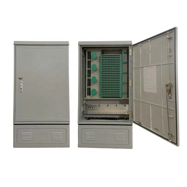
This paper provides practical guidance on preparing your edge sites including how to assess the site's constraints as well as, power, cooling, and network connectivity needs. It also provides guidance on starting up the system. Micro data centers offer a compact, cost-effective alternative to traditional facilities, bringing critical compute and storage closer to where it's needed. Image: Alamy Building a full-scale, traditional data center requires millions of dollars and many months of construction. The focus of this paper is on small server rooms and branch offices. The Micro Data Center design addresses the need for a structured approach to implementing robust, integrated and secure networks in the industrial space. Adhering to Converged Plantwide Ethernet (CPwE) principles, the MDC design represents the basic requirements of the manufacturing environment. designing data centers. Many data centers around the world rely on our fiber-optic and twisted-pair cabling solutions as the physical foun ation of their networks. R&M's Automated Infrastructure Management (AIM) system has also become the basis for automating and orchestrating all MAC processes. This document describes the site requirements for installing the FusionModule2000 6. 0 smart modular data center (smart module for short) as well as the methods for installing cabinets, devices, and cables, providing installation guidance and technical support for onsite installation personnel and.
[PDF]

This document discusses the implementation for Cisco Software-Defined Access (SD-Access) deployments for Airports. For the associated deployment guides, design guides, and white papers, refer to the following documents:. The low noise Silent Switcher architecture simplifies design and PCB layout to help streamline development and reduce the chance of a redesign. The compact Silent Switcher solution size supports a range of applications, including industrial, instrumentation and measurement, healthcare, aerospace. AIRPORT ELECTRICAL DESIGN STANDARDS Los Angeles World Airports 1. 1 GOALS The goal of this section is to provide guidance for all electrical work at LAWA. Additional discipline specific guidance related to electrical work can be found throughout the Design & Construction Handbook (DCH). This page provides a quick reference to engineering, design, and construction standards for various airport-related equipment, facilities, and structures. Visit our Series 150 Advisory Circular Library for a complete listing of current advisory circulars. Simpleway's battle-tested hardware ecosystem combines nnounce audio devices with digital signage controllers, creating a unified communication infrastructure built from real airport experience - from routine gate operations to full-terminal evacuations. Discover how nnounce devices create a.
[PDF]

This guide covers everything: what fiber optic pigtails are, how they differ from patch cords, which connector and polish type to specify, how to choose between mechanical and fusion splicing, and the real-world applications where pigtails are the right call. In this guide, we cover the basics of fiber optic splicing, how to perform splicing using two different methods, and finally some best practices to perform good fiber splicing. What is Fiber Optic Splicing and Why is it Needed? – #1. Whether you're building out an ODF. Think of a fiber optic cable splice as the seamless stitching that keeps data flowing through the delicate threads of a network—like a master tailor joining fabric with precision. Whether repairing a broken cable or extending a fiber run, fiber optic splicing ensures light signals travel. Fibre optic splicing is an essential skill in the world of modern telecommunications, offering a reliable method to connect optical fibres for seamless data transmission. As the demand for high-speed internet and robust communication networks continues to grow, learning to splice fibre optics is. In this guide, you will find a chronological description of the fusion splicing process, the principal technical standards, and answers to the real-life questions network engineers and procurement teams may have. Therefore, we will also touch on cost factors, risk management, and best practices in.
[PDF]

Mechanical Optical Switches: Switching times typically range from 1-10ms, suitable for long-distance transmission scenarios where latency is not critical (such as backbone network protection switching). Solid-State Optical Switches: Based on thermooptic or electrooptic effects, response. We lead the industry in optical switch technology, delivering the lowest insertion loss (0. 2 dB), fastest switching speed (10 ns), broadest wavelength range (300–2400 nm), widest fiber compatibility, highest optical power handling (50 W), and space-qualified reliability. Backed by over 25 years of. Use this optical switches buying guide to compare major types, define selection criteria, and find suppliers: Professional purchasing of high-value photonics products is a substantial responsibility, where a structured decision-making process is essential. RP Photonics offers a lot of help: Get. This document is a troubleshooting and selection guide for common optical switch failures, compiled based on over 500 field cases. These switches are built on proven, reliable optomechanical technology that has seen more than 30 years of successful operation. Each. The POLATIS ® Series 7000 384x384 all-optical circuit switch is designed to meet the most demanding applications with exceptionally low optical loss, compact size, and fast switching speeds. With support for Software-Defined Networks (SDNs) via embedded NETCONF and RESTCONF control interfaces, the.
[PDF]

from outside the US. EMEA Specific: +49 (0) 228 7489 201 HCS and GiHCS are registered tradema time without notice. This document is for informational purposes only and is not intended to modify or supplement any OFS warranties or specifications relating to any of its. from outside the US. STFOC uses our patented cable jacket construction designed to protect the fiber in the harsh subsea environment. Non-KinkTMSTFOC has a patented design to protect. CommScope bundles hybrid cabling to your custom specifications, using our high-performance fiber-optic, unshielded twisted pair and coaxial cables. Devices deployed at the network edge—a 5G radio, a security camera, or an industrial sensor—require high-speed data connectivity and power. It is technically possible to have a separate fiber and electrical cable, but it adds complexity, cost, and maintenance overhead. Optical hybrid cables address. challenge—OCC has what you need. Our team will make sure the configuration is tailored to your needs and will provide a detailed quote. Email us using the Request a Quote below, or give our team a call. Drive, Avon, CT 0600 erat ing Bend Radiu erat ing Bend Radius Cons from outside the US. Teledyne ODI ofers a comprehensive line of fiber optic and electro/optic hybrid wet mate interconnect products. Wet mate connectors are available in ROV Mate, Stab Mate and Manual Mate configurati sm.
[PDF]

In this paper, various operational factors affecting 100G transmission over G. D fiber-cables are discussed to make the right fiber selection for the long-haul network. Selecting appropriate G. 652 fibre was originally optimized for use in the 1310 nm wavelength region but can also be used in the 1550 nm region. This is the latest revision of a Recommendation that was first created in 1984 and deals with some relatively minor modifications. a number of concatenated cable. G. 92% of. Fiber optic cables are the ultimate technology used in data transfer using light waves. They are classified based on wavelength band, core/cladding size, application, and compliance with international standards such as IEC, ITU-T, and TIE/EIA. In the next sections, the real artwork is putting on. This guide explains the most important ITU-T G. 655—to help you make an informed decision for your project, whether it's a long-haul backbone or a final FTTH drop. In the world of fiber optics, not all glass is created equal. The core of every cable—the optical. Because GPON and XGS-PON are deployed in diverse environments, fiber-containing components such as PLC splitters must be evaluated not only by their standard parameters but also by their sensitivity to bending loss, which is critical for maintaining stable optical transmission. The ITU-T defines.
[PDF]