
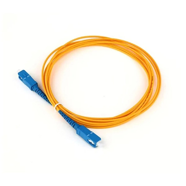
Every fiber optic patch cable has a rated attenuation and bandwidth. For example, OM1 is rated at 200 MHz·km at 850 nm and is intended for use in legacy applications. The higher OM ratings provide more speed and distance. Attenuation should remain within acceptable limits for reliable transmission. Executive Summary: Choosing the right fiber patch cable is one of the most consequential decisions in network infrastructure planning. The wrong choice — whether it's an underperforming multimode grade or an unnecessarily expensive singlemode run — can either cripple your network's reliability or. Fiber optic patch cords are key components for efficient, low-loss optical signal transmission between devices and fiber optic cabling links. One or both ends of the patch cord are equipped with standardized fiber optic connectors, and common interfaces include LC, SC, FC, ST, etc. They are manufactured and tested in compliance with TIA 604 (FOCIS), IEC 61754 and YD/T industry standards. OM1, OM2, OM3, OM4, OM5 or OS2 fiber types are available to meet the demand of. Fiber optic patch cables are ideal for supporting high speed telecommunication network fiber applications. They are lengths of optical fiber terminated with connectors on both ends. Their job is to connect two optical devices, like switches, routers, or optical transceivers that communicate.
[PDF]
Fiber internet provides a higher-capacity connection to your home, which means your Wi-Fi network has more bandwidth to distribute among your devices. This results in faster wireless speeds and a smoother online experience. Although GFiber provides incredibly fast network speeds over wired devices, there are a number of situations to cause your network speeds to slow down. To boost your Internet speed, discover what disrupts or slows your Wi-Fi and wired connections. It acts as a gateway between your local network and the internet, directing traffic between devices and ensuring that data is transmitted efficiently. The type of internet service you have whether it's DSL, cable, fiber-optic, or satellite—can affect speed and reliability. Fiber-optic connections generally offer the fastest speeds and lowest latency. A gig fiber connection will provide around 1,000 Mbps download and 1,000 Mbps upload —but you won't always see those numbers if you run a speed check on your computer. On one hand, a high-quality router can improve network efficiency by optimizing data transmission, reducing congestion, and minimizing errors. On the other hand, a low-performance router or one. Just got Fiber installed, and down speed is phenomenal but I seem to be getting intermittent lag spikes that make things like gaming worse.
[PDF]

Digital Diagnostic Monitoring (DDM) can monitor parameters of the optical module regularly and generate alarms when parameter values exceed thresholds. By using DDM, you can detect issues early to maintain network stability. When you configure the DDM function, follow these notes. Optical Module Monitoring & Troubleshooting 2026 – network-switch. com Digital Diagnostics Monitoring (DDM), also known as Digital Optical Monitoring (DOM) or Diagnostic Monitoring Interface (DMI), is a standardized feature defined by SFF-8472 that allows network devices to monitor real-time optical. Digital Diagnostic Monitoring (DDM), also known as Digital Optical Monitoring (DOM), is a key feature in modern optical transceivers. It can provide the host with real-time data about the module's internal operating conditions, including parameters such as voltage. Digital Diagnostics Monitoring (DDM) is a feature used in optical transceiver modules that enables you to view real-time information about transceivers, such as optical output and input power. For information about which F5 ® transceiver modules support DDM, see F5® Platforms: Accessories. It is an intelligent function that enables network administrators to monitor the transceiver's operational parameters in real time. DDM is not merely a feature; it is an industrialized standard.
[PDF]
Optical data couplers are essential components in modern fiber optic networks. They enable the connection and distribution of light signals between fibers, facilitating high-speed data transmission over long distances. As digital communication demands grow, these devices become increasingly vital. Explore the role, types, and applications of fiber optic couplers in telecommunications and data networks in our in-depth article. They serve an essential role in managing the flow of light. A coupler is an optical device that combines or splits optical signals. Couplers can be used to split an optical signal into multiple signals, combine multiple signals into a. The same kind of device is useful in fiber interferometers, also for combining two inputs. (Note that polarization issues might occur. Unlike active devices like switches or transceivers, couplers require no electrical power to function.
[PDF]

West Port Middle East specializes in engineering and supplying cable management solutions that meet the precise requirements of electrical contracting projects across the GCC. Unigroup offers a line-up of high-performance cable trays, Trunking and Channel Systems for all your cable routing requirements. Our cable tray systems are engineered for modern infrastructure, ensuring safe, organized, and efficient cable routing across commercial, industrial, and utility. Cable Trays are support systems used in building electrical wiring. These cable support systems are commonly used to support insulated power and communication cables. Cable trays provide a more preferable alternative to electrical conduit systems and open wiring. Cable tray systems are generally. Premium Construction: Made from galvanized steel, stainless steel, or aluminum, these trays resist corrosion and provide high load-bearing capacity in harsh conditions. From residential towers to industrial plants, our extensive portfolio of products and accessories is designed to provide. A form of cable management system used for supporting and arranging electrical cables and wires in commercial, industrial, and residential structures is known as GI Cable Tray, also known as Galvanized Iron Cable Tray.
[PDF]

Single fiber modules (BiDi) use one fiber for both transmitting and receiving data. This saves space and money. They are easier to set up and give steady communication. They use a thin fiber. Pioneer LX305 only has 1 optical input, can I add another with some kind of splitter? I love my new receiver but I need a second optical input and I'm wondering what my options are in this regard. Can anyone help? Thanks in advance. Edit: Everyone is going to ask this question, so here are my. The single-mode optical fiber is designed and engineered to carry one single light mode in a minimal core diameter. It is specified as the best for especially long-distance applications than multimode fiber. Due to its. The optical module serves as a crucial component in optical fiber communication systems, operating at the physical layer, which is the lowest layer in the OSI model. Its primary function is to achieve optoelectronic conversion by converting electrical signals into optical signals and vice versa. An. There are single-fiber and dual-fiber optical transceivers. How do we choose, and what are their differences and advantages? Let's learn about this! What is a Single-Fiber (BiDi) Transceiver? Single fiber module also called BiDi transceiver or WDM module.
[PDF]

Single-mode optical splitters are optimized for single-mode optical fiber, while multimode optical splitters are tailored for use with multimode optical fiber. An Optical Splitter, also known as a beam splitter, is a passive optical device that divides a single input optical signal into two or more output signals. Conversely, it can also combine multiple signals into one. Its primary role is in Passive Optical Networks (PON), which are the foundation of. This guide demystifies fiber optic splitters, explaining their design, operating principles, types, key specifications, and real-world applications. It can distribute the optical energy transmitted through a single fiber to two or more fibers in a predetermined ratio or combine the optical energy from multiple fibers into one fiber. “Passive” means it needs no. You use optical couplers and splitters to split or join signals in fiber networks. For example, optical splitters send light to many output ports. This lets you connect more users to one network terminal. There are different types of fiber optic splitters available, with two of the most common being Fused Biconical Tapered (FBT) splitters and Planar Lightwave.
[PDF]

Mainly 9steps: Step 1: cut cable with cutting machines in lengths Step 2: put the connector spare parts on the cable Step 3: Strip cable jacket, coating till bare fiber, and make all parts in ready Step 4: Insert fiber into ferrule, glue dispenser and heat oven Step 5:. Mainly 9steps: Step 1: cut cable with cutting machines in lengths Step 2: put the connector spare parts on the cable Step 3: Strip cable jacket, coating till bare fiber, and make all parts in ready Step 4: Insert fiber into ferrule, glue dispenser and heat oven Step 5:. Learn how to make a fiber optic patch cord step by step, from preparation to testing, for reliable high-performance connections. Most guides on making fiber optic patch cord 1 s feel incomplete. They often focus on the final assembly steps, leaving the foundational stages a mystery. From cable cutting to connector assembly and testing, you will gain valuable insights into the production of. Fiber optic patch cords and Pigtails are very important passive fiber optic components in fiber optic networks. Use the fiber optic cleaver to cut the. This document describes the installation and use of the mode-conditioning patch cords listed in Table 1. A mode-conditioning patch cord is shown in Figure 1 IEEE 802. 3z-compliant optical fiber assembly consisting of a single-mode fiber permanently coupled off-center to a 62. 5-micron multimode.
[PDF]
Tilt sensors are devices that measure the tilt or slope of an object with respect to a reference. Fibre Bragg Grating (FBG) tilt sensors are a specific type of tilt sensor that utilizes the principle of Bragg's law in fiber optics to measure tilt angles. The tilt sensor is composed of two cylindrical floats suspended in water, connected with FBG. When the external environment causes the tilting of the sensor. Abstract—A surface-mounted tilt sensor was designed and fabricated to measure the inclination angle of engineered structures or slopes in two directions. In a FBG tilt sensor, the optical fibre is. We demonstrate a new concept for an all-fiber inclinometer based on a tapered fiber Bragg grating (tFBG) in a fiber ring laser (FRL) with the capability of measuring the tilt angle and temperature simultaneously.
[PDF]

The following are the precautions for the use of Gigabit optical transceivers and 10 Gigabit optical transceivers, some common fault causes, and corresponding troubleshooting methods and solutions. Avoid damage. In the formation of modern networks, optical modules are essential equipment, of which Gigabit optical modules and 10 Gigabit optical modules are popular because of their high speed and stable transmission rate and wide applicability. However, the failure of optical modules is a common problem. 10G SFP+ optical modules remain one of the most widely deployed transceiver solutions in data centers, telecom networks, enterprise switching, and cloud-scale architectures. Their compact size, low power consumption, and versatility across multimode and single-mode fiber make them a critical. Gigabit optical transceivers and 10 Gigabit optical transceivers are an essential part of modern network communication, but they will inevitably encounter some failures during use. This article dives into technical specifications, real-world usage scenarios, selection criteria, and. Single-fiber bidirectional (BIDI) optical modules must be used in pairs. For example, SFP-10G-BXD1 must be used with SFP-10G-BXU1. Cisco XFP Module Main features of the Cisco XFP Module include:.
[PDF]

This guide covers the critical steps, from selecting the right electrical cable tray and performing accurate cable fill calculations to managing a safe cable pull through and ensuring all bonding and grounding requirements are met. But before you lay the first tray or clamp down a single cable, you need a solid plan. This guide breaks down the process step by step. Plan the Route Before You Drill No installation should start without a plan. For licensed electricians, mastering these principles is essential. Cable tray installation implies the construction of an electric road that will be safe. In order to get it right, installers are supposed to adhere to a plan that ensures that wires are kept cool and the building is stable. The beginning of success is to review the Bill of Quantities (BOQ) so that. Cable tray systems provide a safe, organized, and flexible method for supporting insulated conductors and cables in commercial and industrial electrical installations. When properly selected and installed, cable trays simplify routing, improve accessibility, and support future expansion while. Proper installation of cables in trays is critical for maintaining an efficient and safe electrical system. This process is integral to determining the optimal arrangement and configuration of cable trays, which are essential for routing and supporting electrical cables within buildings and.
[PDF]

Within data centers, optical distribution boxes manage fiber connections between servers, switches, and storage devices. They enable high-density fiber management, reducing cable clutter and improving airflow. This use-case enhances data transfer speeds and system uptime. They protect delicate fiber cables from environmental factors like moisture, dust, and physical damage. These boxes are used in various settings, including outdoor street cabinets. Optical fiber distribution box (often referred to as optical fiber distribution box or ODF box) plays a crucial role in optical fiber networks, and its advantages are mainly reflected in the following aspects: First, efficient fiber management Modular design: The optical fiber distribution box. These boxes simplify network expansion and reduce installation complexity by combining fiber distribution and signal splitting functions in one enclosure. FDB is used for the purpose of distributing and terminal connection to numerous types of optical fiber systems. They are commonly used by FTTH clients wiring equipment, in order to provide protective connections. The box is compact, light and is widely used for end termination of villas and. An Optical Distribution Frame (ODF) is a specialized enclosure designed to manage, connect, protect, and distribute fiber optic cables in telecom and data networks. It acts as a central point for terminating, splicing, and distributing these cables, providing necessary protection and.
[PDF]

Learn how to wire tail lights on any vehicle with this simple step by step guide. Whether you're fixing broken lights or installing new ones, this tutorial will help you do it yourself safely and correctly. Watch till the end for wiring tips to avoid common mistakes. more Learn how to wire tail. Photoelectric sensor wiring First, we will show you how to wire the Through-Beam photoelectric sensor emitter. Do not install the switch with the Photocell facing artificial or reflected light. Features Sensing distance ranging from several centimeters to several meters. It emits a beam of light and measures the amount of light reflected or absorbed by the object. Photo eye sensors are commonly used in various industries for. Are you struggling with photoelectric sensor installation and configuration? This comprehensive guide will walk you through everything you need to know about wiring, setting up, and troubleshooting photoelectric sensors in industrial automation applications. Whether you're an experienced engineer. Learning how to wire up a tail light correctly is relatively easy, but it does require some knowledge of electrical systems and tools such as soldering irons and wire cutters. Installing a tail light on your vehicle can provide many benefits. I have looked at the other posts on Chief Delphi and was still baffled. One of the many specific questions would be WHERE do we plug the wires into the RoboRIO? Would it be in the 0-9.
[PDF]

