
We determine the noise coefficients of a Fiber Bragg Grating Accelerometer (FBGA) at static operation using Allan Variance Method. We describe the mechanical structure of the FBGA, as well as the embedded optical and electronic circuits used to acquire the experimental data. Fiber Bragg grating (FBG) sensors have emerged as advanced tools for monitoring a wide range of physical parameters in various fields, including structural health, aerospace, biochemical, and environmental applications. This content is available for download via your institution's subscription. To access this item, please sign in to your. Abstract – Fiber optic Bragg gratings have found increasing applications to seismic strain measurement of underground structures and rock mass. The strain sensitivity of a Bragg grating measuring system, however, is limited by the noise caused by the instability of the laser wavelength and the. Fiber Bragg grating (FBG) sensors have proven to be adaptable for monitoring various physical quantitites like temperature, strain, or even vibrations and acoustic noise. Several interrogation methods, like spectroscopic evaluation, interferometric interrogation, active scanning or active filtering.
[PDF]
This paper presents a method for the CTE measurement of composite specimens using Fiber Bragg Grating (FBG) sensors. FBG sensors consist of periodic refractive index variation made on the core of optical fiber. When a broadband source is given to the FBG, one. Coefficient of Thermal Expansion is defined as where dl is the change in length for the temperature change dT and l is the original length. There are various conventional measurement techniques for the determination of the CTE, namely dilatometry , interferometry and thermomechanical. Measurement of the Coefficient of Thermal Expansion of Materials Access to the requested content is limited to institutions that have purchased or subscribe to SPIE eBooks. You are receiving this notice because your organization may not have SPIE eBooks access. Pure thermoplastic and composite specimens were built using different commercially available filament. A variation of the period of the grating inscripted in a fiber optic – induced by mechanical or thermal perturbation – causes a shift of the reflected peak wavelength, due to the related optical path length variation. where Pij are the Pockel coefficients of the elasto-optic tensor, n is the.
[PDF]
An optical fiber is a cylindrical ( waveguide) that transmits light along its axis through the process of total internal reflection. The fiber consists of a core surrounded by a layer, both of which are made of materials. To confine the optical signal in the core, the of the core must be greater than that of the cladding. The boundary between the core and cladding m.
[PDF]

A weak fiber Bragg grating (WFBG) is an ideal quasi-distributed optical fiber sensor. Special attention should be paid to the spectrum and sensing performance of the WFBG at extreme temperatures due to its poor reflection intensity. In this Letter, the temperature characteristics of the WFBG from. 📦 For purchasing, use the RP Photonics Buyer's Guide for fiber Bragg gratings. It provides an expert-curated supplier directory, buyer-focused technical background information, and structured selection criteria to support professional procurement decisions. What is a Fiber Bragg Grating? What is a. Abstract: Fiber Bragg grating (FBG) array, consisting of a number of sensing units in a single optical fiber, can be practically applied in quasi-distributed sensing networks. Serious signal crosstalk occurring between large-serial of identical FBGs, however, has limited the further increase in the. A multi-parameter measurement system based on ultra-weak fiber Bragg grating (UFBG) array with sensitive material was proposed and experimentally demonstrated. The UFBG array interrogation principle is time division multiplex technology with two semiconductor optical amplifiers as timing units.
[PDF]

Home and business fiber optics projects typically range from a few hundred to several thousand dollars, depending on run length, fiber type, and labor needs. The main cost drivers are materials, installation time, and environmental factors that affect trenching, conduit, and terminations. Commercial building installations with 100-200 network drops generally range from $15,000 to $30,000. Single-mode fiber costs less per foot than multimode fiber, but it requires more. What is Fiber optic network design? Fiber optic network design involves the planning, routing, and drafting of Fiber cable layouts to support high-speed data transmission. It includes detailed mapping of backbone, distribution, and drop connections for FTTH, FTTP, FTTx, and enterprise networks. Fiber optic network design refers to the specialized processes leading to a successful installation and operation of a fiber optic network. It includes first determining the type of communication system (s) which will be carried over the network, the geographic layout (premises, campus, outside. According to ResearchAndMarkets, the global market for fiber optics was estimated at $5. 8 billion in 2022 and is expected to reach $11. This is the dominant broadband access technology across half of OECD countries today. The price landscape varies from basic drop cables to enterprise backbone runs, with per foot and per reel pricing common in estimates. This guide presents cost ranges.
[PDF]

This complete guide explores everything you need to know about ODFs — from their structure, types, and key components, to installation best practices and modern design trends. Whether you're building a central office, data center, or FTTx distribution network, understanding the right ODF. An Optical Distribution Frame (ODF) is the central hub for fiber splicing, termination, patching, and cable protection in modern optical networks. This guide demystifies ODF, exploring their design, core functions, types, and how they. Fiber distribution hardware manages each fiber and connection point that is associated with active electronics. Why do operators, designers, and installers use additional fiber optic hardware racks for cable and fiber management? The active electronics are the most expensive part of the. A bad ODF can cause signal loss, slow repairs, and network outages. Let's talk about ODFs the way engineers and buyers need — with facts, clear advice, and practical steps. It's where. An ODF is a central hub in fiber optic networks, crucial for managing and organizing the variety of fiber-optic cables and connections entering a facility such as a telco central office (CO). Key points An optical distribution frame (ODF) is a central hub in fiber optic networks, crucial for.
[PDF]

This paper presents a set of newly developed modeling, simulation and testing tools aimed at better understanding the design concept and related applications for protective relaying and substation automation solutions for the smart grid. presentation of protection and control relaying. The report will identify methodology behind these practices, present issues raised by the integration of microprocessor relays and the internal logic and external communication configurations, ying. At Keentel Engineering, we specialize in modeling, simulating, and deploying advanced protective relays to ensure the robustness of medium-voltage (MV) and high-voltage (HV) networks. Our engineering services help utilities, OEMs, and renewable developers simulate real-world contingencies and. This Modern Power System Protective Relaying training course has been designed to provide a clear and perfect understanding of power system protection schemes and devices, including protection relays, fuses, circuit breakers, and other protective devices. In modern power systems, nowadays. To ensure that protective relays, circuit breakers, and other protection devices correctly and selectively isolate faults, minimizing damage to equipment and interruptions to customers while maintaining system stability. One-line diagrams and detailed network data (lines, transformers, buses).
[PDF]
When you see “PON” on your router, it stands for Passive Optical Network. This light indicates the status of your fiber connection to the network. Passive optical networking (PON), like active optical networking, uses fiber-optic cabling to provide Ethernet connectivity from a main data source to endpoints. While there are many subtle differences, a clear distinction between active optical networking and PON topology is PON's use of a. A passive optical network (PON) is a fiber-optic telecommunications network that uses only unpowered devices to carry signals, as opposed to electronic equipment. In practice, PONs are typically used for the last mile between Internet service providers (ISP) and their customers. The purpose of an OLT is to control, convert signals and coordinate fiber optic service (FiOS) within a PON system. An ONT. Turn off the router and disconnect the power cord. Locate the optical network (PON) port on your router. Inspect the PON cable for make sure that it is correctly connected to the router. Instead of running a separate fiber strand to every home or office, a PON shares a single fiber using optical.
[PDF]
Unlike, single-mode fiber does not exhibit. This is due to the fiber having such a small cross section that only the first mode is transported. Single-mode fibers are therefore better at retaining the fidelity of each light pulse over longer distances than multi-mode fibers. For these reasons, single-mode fibers can have a higher than multi-mode fibers. Equipment for single-mod.
[PDF]
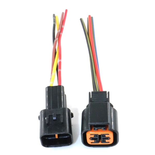
Fiber optic adapters play a vital role in modern optical communication systems by enabling seamless connections between fiber optic cables. These small yet essential components ensure efficient data transmission, reduce signal loss, and maintain system integrity (1). In this article, we'll explore. Explore the essentials of fiber optic adapters, their types, benefits, selection, maintenance, and their role in future tech. They serve as interfaces for connecting fiber optic cables, facilitating. Fiber optic adapters are small but essential components that ensure precise alignment between connectors. Using the wrong type or neglecting cleaning can lead to signal loss and unstable connections., two fiber connectors) such that light can reliably pass from one to the other with minimal insertion loss and maximum return loss. Though fiber optic adapters are small accessories often ignored by technicians, they play a vital role in fiber telecommunications, connecting fiber optic cables and connectors. This article discusses their purposes, features, types, and how to choose and clean them. Most fiber optic connectors are composed of.
[PDF]
Fiber technicians are taught to keep connections clean after termination, cover connector ferrules and mating adapters with dust caps and clean the ferrule end whenever it is opened to the air. Fiber optic cables are a critical component in modern networks, with their performance directly affecting the stability of data centers and enterprise networks. Effective lifecycle management of fiber optic cables, from selection and installation to daily maintenance and replacement, is essential. That advice is misguided. It could hurt an installer or get them sued by an irate network owner. We've created a simple guide on keeping fiber optic cables in good condition without impairing them. Avoid getting them damaged by handling them with extreme care. We've created a simple guide on maintaining.
[PDF]
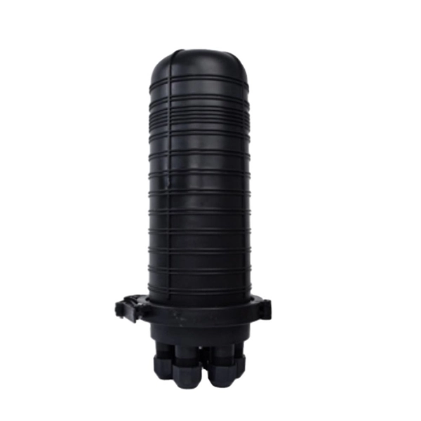
This splice case protect fiber optic cables and juction from outside plant environment damage. They are made of reinforced ABS or PC plastic, which has high strength and corrosion resistance. In addition, the splice enclosures are all hermetically sealing structure, waterproof and. Standard polycarbonate (PC) or Glassfibre reinforced (PC+GLAS) PP ABS (Acrylnitrile-butadiene -styrene) Slightly lower UV resistance compared with PC. Recommended for outdoor use if protected against weather influences GRP – GLASS FIBRE REINFORCED POLYESTER Polycarbonate and ABS enclosure materials. The fiber optic splice closure is a closed structure used for splicing, protecting and managing optical fibers. Its material selection is crucial to ensure the quality and service life of the fiber optic splice closure. These boxes are well suited as optical cable splice collection points for DAS (Distributed Antenna Systems), MTU (Multi-Tenant Unit) commercial business applications, and MDU (Multi-Dwelling Unit). It is a reentry box which is made of PC or PP material. The shells and the base are sealed with silicone gum. This product can be re-entered and used again after it is opened. Typically selected for high-density OSP splicing and branching. What is the basic structure of Fiber Optic Splice Closure? The basic structure of Fiber Optic Splice Closure includes the box body, box components, sealing ring, and lock buckle.
[PDF]

Technical Fiber Optics Lines Factory (TechLine) is a big factory was established in Jordan in 2016 located in Al Qastal industrial area in Amman. It is ISO 9001:2008 certified with a scope distinction of being first of its kind in the Middle East region. It strives to become one of the leading. Techline offers a complete range of Fiber optic passive equipment ranging from FDT, joint closures, enclosure boxes, distribution boxes and frames, and indoor/outdoor fiber cables to be used inside the network from the Central Office to the user. Products are designed for easy installation with the. APAR's Fireoproof Fibre Optic cables are specially designed cables for complying specific fire standards. Fireoproof cables are suitable for communication networks across all emergency systems and other key equipment where fire safety is of utmost importance and are available in customised designs. When a fire breaks out in a data center or a high-rise building, the cabling in your walls acts in one of two ways: The Fuse: It melts, drips, and carries the flame from room to room. The Barrier: It self-extinguishes and stops the spread of toxic smoke. Choosing the right Fire-Resistant Fiber. All feature a corrugated steel tape armour for protection from rodents, a central loose tube construction and internal/external LSZH (Low Smoke Zero Halogen) sheath. The outer sheath is black with a red stripe for easy identification and also provides UV stability. A key feature of the Draka.
[PDF]


