
This paper explores the latest trends in the cable tray manufacturing industry, focusing on technological advancements and sustainable practices. It covers the integration of IoT for smart monitoring, the use of innovative materials for enhanced durability, and modern. In 2025, the landscape of cable management has evolved significantly, with cable trays playing a pivotal role in supporting the complex wiring systems of modern infrastructure. The Global Cable Trays and Ladders Market plays a pivotal role in modern infrastructure, enabling secure and efficient routing of power and communication cables in industrial, commercial, and residential environments. These systems provide structural support, organization, and safety in electrical. The cable tray market is projected to grow from USD 4. 3 billion in 2025 to USD 5. Metal will dominate with a 63. 4% market share, while ladder cable trays will lead the product type segment with a 42. This global Cable Tray Systems market research report provides a comprehensive overview by conducting both.
[PDF]

Recommendation ITU-T L. 101 describes characteristics, construction and test methods of optical fibre cables for buried application. 0, in February 2016. The short answer, based on general industry standards and the National Electrical Code (NEC), is that fiber optic cable is typically buried between 24 inches (60 cm) and 30 inches (76 cm) deep. However, simply hitting this depth isn't enough to guarantee your network survives. Factors like the. Underground fiber optic cable installation follows specific standards that govern burial depth, testing methods, installation techniques, and safety requirements. 5 is an article in the National Electrical Code that addresses requirements for underground electrical installations, including minimum cover requirements—the measurement used to determine the distance from the top of an underground cable or raceway to the finished grade. 5. Estimate minimum burial depth (cover) for underground electrical, fiber, and low-voltage cable runs using a practical, code-aware ruleset. Use this page to plan trench depth, compare conduit options, and prepare for inspection conversations. Use this calculator to estimate a minimum burial depth. Recommendation ITU-T L. This depth is generally considered the absolute shallowest for any telecommunications cable that is not placed.
[PDF]

This article provides a detailed technical comparison between fiber optic and copper cables, offering a clear perspective for engineers, network architects, and procurement managers. The core distinction between the two technologies lies in the physics of data. However, the exponential growth in data demand has positioned fiber optic technology as the superior alternative for performance, scalability, and future-readiness., 10G/25G/40G/100G and beyond depending on optics and reach). Copper Ethernet scales too, but practical limits are lower and depend. The two main options are fiber optic cables and copper cables, each with its own advantages and drawbacks. Fiber optic cables are praised for their high performance and scalability, while copper cables remain a cost-effective choice, especially for budget-conscious projects and older systems. Copper wire is more susceptible to interference and has limited data capacity, making optical fiber the preferred choice for modern high-speed. Optical connectivity, utilizing fiber-optic technology, has emerged as the superior choice for modern networking, offering unparalleled performance, reliability, and scalability. For example, a typical 10 Gbps copper Ethernet link (such as Cat 6A) over 100 meters can consume approximately 5 to 8+.
[PDF]

Compare fiber optic and copper Ethernet cables across speed, distance, cost, installation difficulty, and use case metrics. Use the interactive scenario selector to find the right medium for your specific network — all processed locally in your browser. PoE Required?. The core difference between fiber optic and copper cables lies in how they carry data. One uses light, the other electricity—and that distinction shapes everything from speed to signal integrity. Fiber optics transmit data as pulses of light through ultra-thin strands of glass or silica. Both technologies can deliver high-speed connectivity, but they behave differently under real-world constraints such as. However, the exponential growth in data demand has positioned fiber optic technology as the superior alternative for performance, scalability, and future-readiness. This article provides a detailed technical comparison between fiber optic and copper cables, offering a clear perspective for. Fiber optic tends to be the more premium solution, while copper wiring is far more common, but why is that? What are the differences between these two cable types, and why might you want to pick one over the other? Here's everything you need to know about fiber vs. copper cables, to help you pick. Several factors are converging to drive the switch from copper to fiber – and cost is a big one. A recent investor presentation by AT&T claimed that fiber was 35% less costly to maintain than copper.
[PDF]

On average, commercial projects range from $5,000 to $20,000 per mile underground and $40,000 to $60,000 per mile for aerial deployment. Individual business connections often cost between $15,000 and $30,000 for 100–200 network drops. Buying fiber optic installation services involves several cost components, with total price influenced by length, location, and access. The main cost drivers include trenching or aerial deployment, materials, labor hours, and any required permits. This guide presents typical price ranges in USD to. The initial cost of installing fiber optic cables can vary depending on the chosen installation method and specific project requirements. In preparing this second edition of the Fiber Deployment Cost report, Cartesian gathered inputs from a wide variety of firms building. Getting accurate cost estimates is crucial for winning fiber installation bids. Smart contractors know that underground vs aerial installation pricing varies wildly based on location and project conditions. This breakdown gives you real numbers to build better estimates. We'll show actual costs for. Home and business buyers typically see a wide range of costs for fiber optic projects, driven by distance, fiber type, conduit needs, and labor. The price can shift based on underground vs. aerial routes, equipment choices, and whether new permits are required. Some variables are less determinate.
[PDF]

In telecommunications, a base station is a fixed transceiver that is the main communication point for one or more wireless mobile client devices. It further connects the device to other. A communication base station is composed of a computer room, base station, antenna, feeder line (transmission line between transmitter and antenna), and supporting equipment. The antenna is at the top of the signal tower, and below the tower is a computer room. Along with increased capacity demands driven by the explosion of cloud and connected device growth, engineers need interconnects that enhance the design. A base transceiver station (BTS) or a baseband unit (BBU) is a piece of equipment that facilitates wireless communication between user equipment (UE) and a network. UEs are devices like mobile phones (handsets), WLL phones, computers with wireless Internet connectivity, or antennas mounted on. Fiber Optic Cables: High-speed fiber optic cables connect the BBU to the RRUs (RE part). Signal Transmission: The optical signals carry data, control, management, and synchronization information. Topology: The BBU and multiple radio heads can be connected in cascade or star configurations. The rise. The design investigates the possibilities of Free-Space Optical (FSO) communication systems and MilliMeter-Wave (MMW) technologies operating at 60. Although these technologies are highly effective and have a high throughput, they are nevertheless vulnerable to weather phenomena like rain.
[PDF]

A distribution box, also known as a junction box or distribution point, is a enclosure or housing used to distribute electrical or telecommunications cables to multiple directions. A distribution box (DB box) is a key part of electrical wiring, acting as a central hub where cables branch out to various outlets and switches in a building. It supports different cable sizes and types, enabling smooth and fast power distribution. Each. Distribution boxes, also known as electrical distribution boards or panels, are pivotal components in electrical systems, ensuring the safe and organized distribution of electrical power throughout residential, commercial, and industrial environments. These boxes house various circuit breakers. With the new distribution box, centrally routed cables can be distributed 360° in all desired directions. Cables with and without connectors can be routed, sealed with IP54 (acc. to 60529) and strain relieved in accordance with EN 62444. This article will provide a detailed introduction to electrical distribution boxes, including their functions, components, types, and uses. Today, electrical systems are essential for homes and industries. But what exactly is a power distribution box, and why is it so essential in our daily lives? The DB panel board controls the flow of electricity.
[PDF]

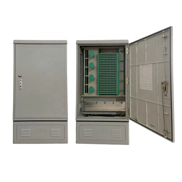
Fiber optic terminal boxes provide functions such as input, branching and splicing of optical fiber cables. Through the connectors and splicing boxes in the terminal box, optical fibers can be quickly connected and repaired. Serving as a critical connection point, FTB facilitates the termination, splicing, or connection of fibers from various cables to other network devices such as switches, routers, or Optical Network Terminals (ONTs). It aids in splicing, splitting, storing, and managing fibers within the appropriate. The optical fiber terminal box is the terminal joint of an optical cable, one end of which is an optical cable, and the other end is a pigtail, which is equivalent to a device that splits an optical cable into a single optical fiber. A fiber pigtail is a specific hardware connection used for cable termination. It is a small enclosure that can house and protect the fiber optic cables, splices, and connectors. The optical fiber termination box and optical fiber splice box serve distinct purposes and are not interchangeable.
[PDF]

Urban Areas: 25–40m spacing (concrete poles, 10–12m height)., steel lattice structures). Factors: Cable weight (kg/km) Ice loading (up to 50mm. The Fiber Optic Association, Inc. (FOA) was founded in 1995 to help develop the workforce to build the fiber optic networks to support a rapid expansion in communications and the Internet. The charter of the FOA was to promote professionalism in fiber optics through education, certification, and. to n utral comm. cable R. FO-CS JOINT USE CLIMBING SPACE REQUIREMENTS 51. APPENDIX A - COVER SHEET / TOC 52. RUS DRAWING #PM12 58. CHECK. d suppliers of electrical construction services. They define a minimum baseline of quality and workmanshi for installing electrical products and systems. NEIS® are intended to be referenced in contrac documents for electrical construction ation or liability to users of this publication. Choose the type of pole The basic pole height is 7m and the tip diameter is 150mm. In case of special sections, crossing obstacles or roads or railways, the pole height of 8m, 9m, etc. can be selected. Cables 300 V or less need to be a minimum two feet over the street light. Climbing Space is an unobstructed, vertical space along the side or corner of the pole. In gen-eral, it consists of an imaginary box, 30-inches square, extending at least 40 inches above the highest communications cable or.
[PDF]

The OPPC cable (Fiber Optic Composite Aerial Phase Conductor) is an innovative optical cable that integrates electrical power transmission and optical fiber communication. By incorporating fiber optic units inside the phase conductor, it ensures both energy transmission and. Electrical utilities have networks used to transmit and distribute electrical power over a large geographic area. In their served areas will be power generating stations, alternative energy sources (solar, wind, geotherman, etc. ), substations for distribution and microgrids. These networks must be. wer transmission systems. The cable is used in power transmission lines, due to its excellent performance in low and medium-voltage electrical networks. This article will provide some knowledge of OPPC cable. What is OPPC. Optical Phase Conductor (OPPC) is used as an alternative telecommunications solution when there is no existing ground wire, meaning Optical Ground Wire (OPGW) is not a viable option. It combines optical fiber technology with traditional conductors, enabling real-time monitoring, improved performance, and increased reliability of.
[PDF]

No, single-mode SFPs are designed to work with single-mode fiber cables and multimode SFPs are designed to work with multimode fiber cables. Attempting to use a single-mode SFP with a multimode fiber cable could result in poor network performance or data transmission errors. It utilizes ultra-low optical attenuation for medium to long transmission. The single mode SFP generally uses high-cost FP and DFB lasers with long wavelengths to optimize. Single-mode (SMF) and multi-mode fiber (MMF) use different core sizes, sources and wavelengths. Understanding the compatibility constraints prevents costly downtime and troubleshooting. To address this question, it's important to understand the characteristics of both single-mode and multimode fiber optics, as well as the implications. Multimode fiber (MMF) uses a larger core diameter (typically 50 or 62. 5 microns) allowing multiple light modes to propagate, suitable for short distances. In contrast, single mode fiber (SMF) has a smaller core diameter (~9 microns) supporting one mode of light, enabling longer reach with minimal. SFP modules are compact, hot-swappable devices used in networking equipment to facilitate the connection of fiber optic cables. They come in two primary types: single-mode and multimode. Single-mode SFPs are designed for long-distance communication, typically using a laser as the light source, and.
[PDF]
This cabling system organizes and manages fiber optic cables and copper cables through cable trays, patch panels, and structured cabling systems, enabling easy maintenance and scalability. Fiber and Cat6a can run together in shared trays when properly separated. Protect the fiber bend radius at all transition points. Avoid stacking heavy copper bundles on delicate fiber. Separate power cables from data cabling. Prevent tray overcrowding to maintain airflow. Wire mesh trays enhance. Data center cabling refers to the organized system of cables and related infrastructure to connect and manage the various components within a data center. This system ensures efficient data transmission and reliable connectivity in a data center environment. Structured cabling is a methodical. As data centers continue to grow in complexity and scale, efficient fiber optic cabling is essential for maintaining high performance, reliability, and scalability. Cabling not only supports current performance but also ensures future adaptability. Proper planning and implementation of cabling infrastructure can significantly reduce downtime, improve airflow, and ensure.
[PDF]

Start with the simplest, fastest checks (visual inspection, cleaning, cable routing) and only move to instrumentation (power meter, VFL, OTDR) when those steps don't clear the fault. This saves time and prevents needless part swaps. HOLIGHT Fiber Optic provides factory-direct, high-performance cables, adapters, and cleaning tools for telecom, FTTH, and industrial applications. What are the most common signs of fiber cable damage? Visible cracks, flattened jackets, sharp bends, dirty connectors, and corroded ferrules are. Fiber optic cables are the backbone of modern high-speed internet, television, and communication systems. Designed to transmit data using light pulses, these cables offer exceptional speed, bandwidth, and reliability. While these cables are engineered for durability (with some rated to last 25+ years), they are not invulnerable. Accidental cuts, breaks, or other damage can disrupt your network and cause costly downtime. With the right tools and techniques, you can efficiently repair damaged fiber cables and restore. Fiber optics is a technology that utilizes thin strands of glass or plastic, called optical fibers, to transmit data in the form of light pulses. This technology has revolutionized the field of telecommunications, offering significantly higher bandwidth and faster signal transmission compared to.
[PDF]