
In this guide, we'll walk you through the entire process of preparing fiber optic cable for splicing and termination to fiber connectors. We'll explore the necessary tools, safety precautions, and step-by-step procedures for cable connectors, mechanical and fusion. At the heart of any robust fiber optic network lies a crucial process: Preparing a fiber cable for termination of a connector or splice. Two types of splices are used in fiber optic cabling one is Mechanical the other is Fusion. Whether you're installing a new network, expanding an existing one, or. Splicing fiber optic cable is an extremely important phase for making dependable, high-speed communication infrastructures. Regardless of the type of fiber network you're deploying, be it for telecom, enterprise data centers, or smart city infrastructure, fusion splicing provides the benefits of. Think of a fiber optic cable splice as the seamless stitching that keeps data flowing through the delicate threads of a network—like a master tailor joining fabric with precision. This article explains when. We terminate fiber optic cable two ways - with connectors that can mate two fibers to create a temporary joint and/or connect the fiber to a piece of network gear or with splices which create a permanent joint between the two fibers. These terminations must be of the right style, installed in a. So in essence, fiber optic splicing is a process used to join two separate fiber optic cables together.
[PDF]

An optical module sends data as light through fiber cables. Light is faster than electricity, making it great for quick communication. The optical module serves as a crucial component in optical fiber communication systems, operating at the physical layer, which is the lowest layer in the OSI model. Its primary function is to achieve optoelectronic conversion by converting electrical signals into optical signals and vice versa. This technology is crucial for fast and reliable data transfer in networks. Optical modules typically have an electrical interface on the side that connects to the inside of the system and an optical interface on the side that connects to the outside. Optical fiber transmission forms the backbone of modern high-speed communication networks, enabling the efficient transfer of massive datasets across vast distances. These modules typically consist of a transmitter, which converts electrical signals into a light signal, and a receiver, which converts the received signal back. In high-speed data networks, the seamless integration of fiber optic cables with SFP (Small Form-Factor Pluggable) modules is critical for reliable signal transmission. SFP transceivers bridge electrical and optical signals, making them indispensable in data centers, telecom networks, and.
[PDF]

Fiber optic communication relies on transmitting information as pulses of light through thin strands of glass or plastic called optical fibers. Instead of using electrical signals (like in traditional copper wires), it uses electromagnetic radiation in the form of light. This method encodes data into light signals by modulating properties like wavelength, phase, and polarization. The light signals propagate to the receiver through the fiber optic cable. Optical fiber. Okay, let's break down the use of electromagnetic radiation (specifically light) in fiber optic communication. It's a fascinating and crucial technology! Here's a comprehensive explanation, covering the basics, the types of light used, how it works, advantages, and some challenges. The light is a form of carrier wave that is modulated to carry information. This method of data transmission has gained substantial significance in modern communication networks due to its capacity to deliver high-speed internet and other forms of. By using the phenomenon of total internal reflection, light can be transported over long distances without reduction of the energy density due to divergence of the beam. The principle has been known for a long time, but the topic was greatly boosted by the invention of the laser.
[PDF]
Splicing allows you to restore or expand fiber networks while maintaining signal integrity. When done right, splicing ensures minimal loss and long-lasting performance. This is where fiber optic cable splicing—the process of creating a permanent, high-performance join between two fiber ends—becomes critical. For network managers and technicians, a poor splice can lead to significant signal degradation, network downtime, and costly troubleshooting. At Turn-Key. To begin, the standard definition of splicing in optical fiber is joining two fiber optic cables together. The other, more common, method of joining fibers is called termination or connectorization. Splicing is most commonly used in the field but has application in cable assembly houses. Whether repairing a broken cable or extending a fiber run, fiber optic splicing ensures light signals travel. Whether you're installing new cables or repairing damaged ones, splicing techniques play a vital role in maintaining signal integrity. Choosing the right method affects performance, cost, and long-term durability. In this blog, we'll explore the main types of fiber optic splicing techniques, their. Joining two optical fibers at the right place so that light can be transmitted through them with minimal loss and reflection is known as splicing. Fiber optic splicing is done through two main methods. In fusion splicing, the ends of the fibers are welded together with heat. This guide will walk you.
[PDF]

This article provides a detailed technical comparison between fiber optic and copper cables, offering a clear perspective for engineers, network architects, and procurement managers. The core distinction between the two technologies lies in the physics of data. However, the exponential growth in data demand has positioned fiber optic technology as the superior alternative for performance, scalability, and future-readiness., 10G/25G/40G/100G and beyond depending on optics and reach). Copper Ethernet scales too, but practical limits are lower and depend. The two main options are fiber optic cables and copper cables, each with its own advantages and drawbacks. Fiber optic cables are praised for their high performance and scalability, while copper cables remain a cost-effective choice, especially for budget-conscious projects and older systems. Copper wire is more susceptible to interference and has limited data capacity, making optical fiber the preferred choice for modern high-speed. Optical connectivity, utilizing fiber-optic technology, has emerged as the superior choice for modern networking, offering unparalleled performance, reliability, and scalability. For example, a typical 10 Gbps copper Ethernet link (such as Cat 6A) over 100 meters can consume approximately 5 to 8+.
[PDF]

This article will give you an overview of the use cases for fiber-optic networking, some of the terms used in fiber networking, and suggestions for setting up a fiber network. Once you understand the basic concepts, you can check out my Recommended Equipment section toward. Fiber tapping is a network tap method that extracts signal from an optical fiber without breaking the connection. Tapping of optical fiber entails diverting some of the signal being transmitted in the core of the fiber into another fiber or a detector. Fiber to the home (FTTH) systems use beam. Optical fiber is a technology used to transmit data by sending short light pulses along a long fiber, which is typically made of glass or plastic. In optical fiber communication, metal wires are preferred for transmission because the signals travel more safely. Optical fibers are also resistant to. Photo: Light pipe: fiber optics means sending light beams down thin strands of plastic or glass by making them bounce repeatedly off the walls. This is a simulated image. Note that in some countries, including the UK, fiber optics is spelled "fibre optics. " If you're looking for information online. This manual covers everything about fiber optic cables, how they work, where they are used, and what is new in this area of technology. The choice of fiber optic cable depends on the specific needs of the application, as well as the.
[PDF]

The document discusses optical detectors used in fiber optic communications systems. It describes the functioning of PIN photodetectors and avalanche photodetectors (APDs). Their performance. An optital detector is a device that converts light signals into electrical signals, which can then be amplified and processed. Such detectors are one of the most important components of an optical fiber communcation system and dictate the performance of a fiber optic communication link. PIN Photodiode A PIN photodiode is a widely. Detectors perform the opposite function of light emitters. The most common detector is the semiconductor photodiode, which produces current in response to. It explains how these devices use optical fibers to measure quantities like temperature, mechanical strain, pressure, and vibrations by detecting changes in light propagating through the fiber. A central focus is on sensors based on fiber Bragg gratings, where the Bragg wavelength is sensitive to. Optical Power Meters: These devices measure the power of optical signals in fiber optic cables. This information helps in maintaining signal integrity and quality across the.
[PDF]
These electrical signals need to be converted into optical signals before being sent over long distances. This conversion is done using a device called a transceiver. These light pulses are then sent through the fiber. Fiber-optic communication is a form of optical communication for transmitting information from one place to another by sending pulses of infrared or visible light through an optical fiber. The light is a form of carrier wave that is modulated to carry information. Fiber is preferred. A small form-factor pluggable, or SFP optic module, helps connect network devices fast. It also changes optical signals back into electrical signals. This lets you send data far away. SFP modules work in many network. Optical fiber is the carrier for optical signal transmission.
[PDF]
This article is about the Internet Outages Map, which provides a visualization of global internet health over the last 24 hours. It also includes information on how to use this map and what data it collects, as well.
[PDF]

How to Install a Fibre Connector into a Patch Panel (Easy fibre optic connector installation) How to Install a Fibre Connector into a Fibre Optic Patch Panel. How do you install fibre optic connectors?. Connecting a fiber patch panel to a switch is a critical step in setting up a fiber optic network. There are different types of connectors. In today's high-performance networks, fiber optic patch cables are the lifelines that ensure smooth data flow across switches, servers, and routers. Even the most advanced optical transceivers can only perform at their peak when paired with properly installed, clean, and precisely managed fiber. Choose an SFP module based on the fiber optic cabling that will be connected to the network switches. SFP transceiver modules almost always require two fiber optic cable strands. A Fiber Patch cord connects two devices. You plug it into a switch, router, or patch panel. It's ready to use out of the box. A pigtail is for splicing. You fuse it to a. With a railroad switch (patch panel), the train (data) can travel from A to B, C and even more destinations, otherwise it can only go from A to B, or C to D. This article, What Is a Patch Panel Used for?, has explained it thoroughly.
[PDF]
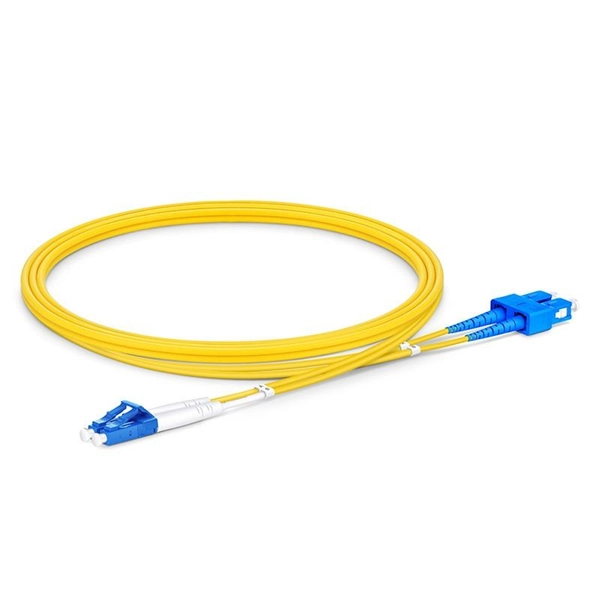
The fiber connector types, sometimes referred to as terminations, link fiber optic cables together through terminals, switches, adapters, and patch panels, by bridging the gap between their internal glass fi.
[PDF]

This guide walks you through the complete fiber installation process, from checking availability to optimizing your Wi-Fi network performance. Upgrading to fibre internet involves replacing your existing copper cables with new fibre-optic ones. This upgrade brings faster speeds and more reliable connectivity. Here is what the installation process is like: One of our technicians will visit your home, remove the old copper wiring and. If you need Fiber Optic Cable Installation in Malta or areas close by allow us to assist you by connecting you with specialized pros who can do the work you request. Step 1: Planning Before any installation begins, thorough planning is essential. This includes determining the network's requirements, such as bandwidth, distance, and the number of. This guide will explain the entire set of activities involved in installing Fiber optic cable contractors -from the early planning stage right through testing-for facility managers, IT teams, and low-voltage contractors to build high-performance networks safely and efficiently. The processes. The Fiber Optic Association, Inc. (FOA) was founded in 1995 to help develop the workforce to build the fiber optic networks to support a rapid expansion in communications and the Internet. The charter of the FOA was to promote professionalism in fiber optics through education, certification, and. We offer :- For more information email us on sales@merlin.
[PDF]

A massive outage has been reported in the Los Angeles area on Father's Day after internet and cable provider Spectrum linked the issue to "criminal acts of vandalism. " "We are currently working on a Fiber cut affecting the Los Angeles area. We are sorry for the inconvenience this. SPARTANBURG COUNTY, S. (WSPA) – Spectrum is offering $25,000 for information leading to the arrest of a suspect accused of cutting and damaging cable lines. Officials said a fiber optic line was intentionally cut, resulting in temporary outages in parts of Spartanburg County, including Inman. Authorities in Spartanburg County, South Carolina, are searching for a vandal who they say cut fiber optic lines Sunday morning. Spectrum says the lines were intentionally cut, resulting in a temporary outage for residents and businesses. In a statement, a Spectrum spokesperson writes, "Criminal. ©2025 NewsBreak. The incident is being treated as an attempted theft. 'The Free Press' reporter Madeleine Rowley discusses the reality behind President Biden's broadband internet project on 'The Bottom Line. Domestic Violent Extremists (DVEs) have increasingly discussed targeting. Several Spectrum lines cut and laid out as repairs continue to restore services throughout the Long Beach area in Signal Hill Thursday, June 19, 2025. Photo courtesy of Spectrum. An internet outage across large parts of Long Beach was caused by someone who intentionally cut fiber optic lines “in a.
[PDF]


