
Plan your outdoor fiber installation carefully by surveying the site, choosing the right cable type, and following FOA and OSP standards to ensure reliability. Select the best installation method—direct burial, aerial, conduit, or underwater—based on your environment and. Underground cables are pulled in conduit that is buried underground, usually 1-1. 2 meters (3-4 feet) deep to reduce the likelihood of accidentally being dug up. In extreme cold climates, cables may need to be buried at greater depths where there temperatures are colder and frost penetrates to. We are Jera line, a factory that produces cable infrastructure products. FODB-8 is installed with adapters, splitters, drop cable patchcords, pole bandings, and fiber cable slack storage. Use. pport cables and splice enclosures. Cost of rack Wire Splice B x (200 (50' Mi As ve 1'-0" wide (min) concrete apron. rons shall be sloped away from box. Cost of apron o d oun. FTTP or fiber To The Premises applications have reinforced the importance of reliable and stable fiber optic terminations. Good quality fiber laying and termination systems help achieve minimal back reflection and low signal loss. They also feature resistance to moisture, impact, chemical exposure. Fiber optic cable may be installed indoors or outdoors using several different installation processes. Outdoor cable may be direct buried, pulled or blown into conduit or innerduct, or installed aerially between poles.
[PDF]
This guide will walk you through every step of the process, from selecting the right materials to securing connections and ensuring safety. Whether you're a seasoned professional or an enthusiastic DIYer, our detailed instructions will equip you with the knowledge and confidence to tackle this. Learn how to properly install an electrical box safely and efficiently. In this step-by-step tutorial, we'll cover: ✅ Tools you need. Covers wiring, placement, standards, and expert tips for a compliant setup. A distribution box is the heart of any electrical system. It takes the incoming power and safely distributes it to different circuits throughout your building. A neutral bar kit is a fundamental component within an electrical service panel, often called a breaker box, designed to manage the flow of electricity in a home or building. This metal strip serves as the termination point for all neutral conductors from the branch circuits. By consolidating these. Before starting the installation, finding a proper place for putting the distribution box is crucial, because it largely decides the safety and convenience of maintenance. Let's see what factors need to be taken care of when choosing the installation place. Beginning of dialog window. Escape will cancel and close the window.
[PDF]

There are many types of boxes used for various functions in PV applications. This article will serve as a guide to the most commonly used ones. In the image below, we see the PV array feeding into first a junction box, then a combiner box, then ultimately to the. A junction box for solar panels is a key component that functions as the central hub of electrical connections of the solar cells. Using a junction box for a photovoltaic system ensures the safe and efficient transfer of electricity generated by the solar panels to the rest of the system. This comprehensive guide explores the role, types, selection criteria, assembly, and. Protect your solar wiring and components with the right junction box. We review 20 waterproof, IP-rated options with real specs and ratings. Disclosure: This post may contain affiliate links. As an Amazon Associate, we earn from qualifying purchases. Ratings. electronics, which feeds generated AC power to the Grid. Other than PV Modules and Inverter/Inverters, the system consists of Module Mounting Structures, appropriate DC and AC Cables, Array Junction Boxes (AJB) / String Combiner Boxes (SCB), AC and DC Distribution G id is available w modules. One such crucial component is the solar junction box.
[PDF]

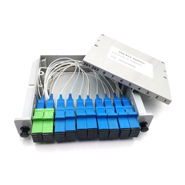
This article provides a comprehensive guide on installing fiber optic patch panels, integrating practical installation steps with insights from business intelligence and data analytics. How to Install Fiber Optic Patch Panel Only by taking the proper steps can achieve a reliable network. For your convenience, the patch panel installation guide is divided into two sections. A successful project begins with careful planning. Whether you are a seasoned professional or new to the field, this guide is designed to enhance your understanding. ⚡ Level Up Your Fiber Skills – Join the One Up Techs Skool 👉 https://www. com/oneuptechs Please like, Subscribe, and comment any questions you may have. com/oneuptechs Most techs struggle because they: ❌ Don't. Keeping this page as a placeholder for now. What are the best practices for fiber patch panel installation? The best practices below help to avoid installation issues and ensure ease of service for the system. Penetrate the enclosure from the side or bottom to minimize the risk of water intrusion. Install grommets on all openings before. The fiber optical patch panel is convenient for people to easily access the optical fiber cable in the panel box, and can protect the optical fiber cable well. In addition, the drawer type structure is also conducive to high-density wiring and good cable management. However, because the optical.
[PDF]

It plugs into network equipment (like switches, routers, or servers) and its primary function is to convert electrical signals from the device into light signals for transmission over fiber optic cables, and then convert received light signals back into electrical signals. People can also refer to an optical transceiver as a fibre optic transceiver or optical module. A transceiver is a mix of the words 'transmitter' and 'receiver. ' An optical transceiver includes an optical. This section explains the core IP and optical components used in traditional hierarchical networks. It helps readers understand the router, transponder, ROADM, amplifier, and management elements that form the baseline network architecture. In fiber optics, this data is sent in the form of pulses of light over an optical fiber, at very high speeds and across long distances. Essentially, these devices. Why choose Nokia for your optical network? The Nokia industry-leading optical network portfolio leverages highly vertically integrated coherent optical engines and includes the latest generation of open and flexible optical line systems, intelligent coherent pluggables, ultra power-efficient. This page provides an introduction to optical wireless networks. It compares short-range (directed and diffused) and long-range optical wireless technologies, highlighting their differences. The broadband wireless.
[PDF]

That is, a distribution electric box is arranged under the general distribution box, and a switch box is arranged under the switch box, and electrical equipment is arranged under the switch box to form a three-level distribution. It's better to replace the 2. "Two-level protection" mainly. The three-level distribution system refers to a system that distributes electric power through three levels of distribution devices from the incoming power line at the construction site to the electrical equipment. "Two level protection" mainly refers to the use of leakage protection measures. In. This subpart addresses electrical safety requirements that are necessary for the practical safeguarding of employees in their workplaces and is divided into four major divisions as follows: (a) Design safety standards for electrical systems. These regulations are contained in §§ 1910. 302 through. Level 3 Protection: Terminal Equipment Surge Protection In lightning protection, the surge protection device in distribution boxes plays a crucial role.
[PDF]

This article will give you an overview of the use cases for fiber-optic networking, some of the terms used in fiber networking, and suggestions for setting up a fiber network. Once you understand the basic concepts, you can check out my Recommended Equipment section toward. Fiber tapping is a network tap method that extracts signal from an optical fiber without breaking the connection. Tapping of optical fiber entails diverting some of the signal being transmitted in the core of the fiber into another fiber or a detector. Fiber to the home (FTTH) systems use beam. Optical fiber is a technology used to transmit data by sending short light pulses along a long fiber, which is typically made of glass or plastic. In optical fiber communication, metal wires are preferred for transmission because the signals travel more safely. Optical fibers are also resistant to. Photo: Light pipe: fiber optics means sending light beams down thin strands of plastic or glass by making them bounce repeatedly off the walls. This is a simulated image. Note that in some countries, including the UK, fiber optics is spelled "fibre optics. " If you're looking for information online. This manual covers everything about fiber optic cables, how they work, where they are used, and what is new in this area of technology. The choice of fiber optic cable depends on the specific needs of the application, as well as the.
[PDF]

Fiber optic cable suspension clamp installation manual made by Jera line. Developed to provide a quick access to attach the fiber optic cable to the pole, using the suspension clamp HC-8-15, stainless steel band, buckles and strapping tool MBT-004. more. This guide will explain the entire set of activities involved in installing Fiber optic cable contractors -from the early planning stage right through testing-for facility managers, IT teams, and low-voltage contractors to build high-performance networks safely and efficiently. The processes. You simply can't handle and install fiber optic cable using the same methods that are used for copper. The relative fragility of fiber when compared to copper cable requires special care, special practices, and attention to detail during handling and installation. (FOA) was founded in 1995 to help develop the workforce to build the fiber optic networks to support a rapid expansion in communications and the Internet. The charter of the FOA was to promote professionalism in fiber optics through education, certification, and. The FIBERLIGN Suspension uses a combination of structural reinforcing rods (SRR), outer rods, housing halves, and resilient inserts to reduce compression, clamping, and bending stresses on OPGW and the optical fibers within it. SRR and outer rods cannot be reused. Different environments demand different fiber optic cable installation methods: aerial cables strung on poles.
[PDF]

The process involves a combination of national infrastructure, local engineering, and property-level setup. In this guide, we'll break down the fiber installation process from start to. This guide walks you through the complete fiber installation process, from checking availability to optimizing your Wi-Fi network performance. Fiber transmits data using light signals through glass strands, delivering faster speeds and lower latency than cable or DSL connections that rely on. In this article we'll break down how fiber internet is installed - from the network fiber drop outside your house to the in-home setup with your router and gateway - and what you should expect at each stage. Fiber optic internet is generally installed in the following 5 steps, which we'll dive. Want lightning-fast internet at home? Fiber optic installation is the way to go! It's super reliable and perfect for streaming, gaming, or using multiple devices. This guide breaks down the process in easy steps so you know what to expect. BCS Consultants, a trusted fiber optic installation company based in California, provides end-to-end fiber optic services, including expert planning. However, setting up a fiber optic connection to your router can seem daunting if you're unfamiliar with the process. In this guide, we'll walk you through how to connect a fiber optic cable to a router safely and efficiently. Why Use Fiber Optic Internet? Before diving into the setup, let's quickly.
[PDF]

A junction box contains four trade size 3 raceways: two on the left side, one on the right side, and one on the bottom. Once conductors have to turn, be pulled through, or be spliced inside an enclosure, the box dimensions start affecting installation time, conductor damage risk, and inspection results. A raceway design that looks fine in a panel schedule can still become a problem if the box is too short for an. Pull boxes, junction boxes, and conduit bodies must be sized to allow conductors 4 AWG and larger to be installed without damage to the conductor insulation. The NEC provides sizing requirements in 314. The distance between raceway entries enclosing the same conductor must be at least 6 times the trade. To size a junction box correctly, first decide whether NEC 314. Use box-fill rules for splices and devices, and pull-box rules for large conductors and raceways. The most common mistake is using the wrong. NEC 314. 28 specifies the minimum size requirements for pull and junction boxes in electrical installations. Proper sizing ensures conductors can be installed without damage and allows for proper bending space. How Does the Calculator Work? The calculator uses NEC 314. Minimum Length = 8 × Largest Conduit Size Minimum Dimension = 6 × Largest +.
[PDF]

In this guide, we break down the two core stages of optical fiber manufacturing: preform production (shaping the precursor material) and fiber drawing (transforming the preform into thin, usable fiber). Optical fiber preforms are the starting point behind every kilometer of fiber optic cable. Though rarely seen by end users, these cylindrical glass rods serve as the base material from which high-speed optical fibers are drawn. As global communication relies more than ever on fiber networks—from. 📦 For purchasing, use the RP Photonics Buyer's Guide for fiber preforms. It provides an expert-curated supplier directory, buyer-focused technical background information, and structured selection criteria to support professional procurement decisions. During the fiber drawing process, the preform is heated and drawn into a. The production of optical fiber is a precision-driven process that transforms raw materials like silicon tetrachloride into ultra-thin, high-performance fibers capable of transmitting terabits of data over thousands of kilometers. Who invented optical fiber and when? Corning scientists Dr. Peter Schultz, and Dr.
[PDF]

In this video, I have explained and verified the Telnet & SSH configuration on an H3C Switch (Model 6520). As shown in Figure 1, the AC is a Telnet server. Make sure the network connections are available. Click the System View tab at the bottom of the page. From the navigation pane, select System > Resource. On the IPv4. To create a user on an H3C switch, you can perform this operation through a web interface or SSH. Follow the commands below to create a user: Specify the user's access level. The same CLI commands and configuration steps can also be applied to other H3C switch models. You will be in the AUX user interface if you log in through this port. 2 User Interface Number Two kinds of user interface index exist: absolute user interface index and relative user interface index. H3C S5100-SI/EI Series Ethernet Switches Chapter 1 Logging In to an Ethernet Switch 2) A relative user interface index can be obtained by appending a number to the identifier of a user interface type. The relative user interface indexes are as follows: z z. Add the specified port to the current VLAN Configure the link type of the port as Trunk type Allow the specified VLAN to pass through the current Trunk port Set the default VLAN for the trunk port Configure the link type of the port as Hybrid View the VLANs that exist on the current switch View the.
[PDF]
Many engineers don't know how to install this accessory. With the latest design, it can be confusing. So here is the instruction: 1. Determine the right height and the quantity of mounting bracket needed 2. Fix it on the gland. Distribution box installation How we make electrical enclosure more Easier DIY tool at home This DIY Woodworking Tool Changes Everything. If provided, proper installation of an equipment grounding terminal must be made and the rack must be grounded in accordance with NFPA 70, NEC, and the applicable sections of ANSI C2, “National Electrical Safety Code. " The equipment shall be installed by trained service personnel. All parts such as. Embarking on a Unistrut installation project can be both exciting and daunting. Whether you're venturing into medical support systems, ceiling grids, roof walks, or catwalks, ensuring a seamless installation requires careful planning and execution. In this guide, we'll delve into some expert tips. Whether you are an electrical contractor or a construction brigade, knowing how to properly and safely install distribution boxes is the basis of ensuring the safe operation of the entire system. This article details the process of installing them, which helps you comprehend distribution boxes. Before you buy electrical boxes, you want to be certain they have the right mounting holes for the devices you plan to install. Also be sure the boxes have correctly placed.
[PDF]