
In this video, we'll show you how to connect an energy meter to a distribution board (DB) safely and efficiently. energy meter connection with distribution box How to Connect an Energy Meter to Your Distribution Box Easily Steps to Properly Connect Your Energy Meter to a Distribution Box. Then I fix the box securely, route and terminate cables neatly, seal against weather, label clearly, and verify all connections before the utility energizes the service. I. Step-by-step guide to installing an electric meter box. Learn safety tips, wiring steps, troubleshooting, and when to call a pro. An electric meter box measures how much electricity your home uses. It helps the utility company give you the right bill. Installing an electric meter box might seem like a job for professionals only—but with the right knowledge, it's a task many homeowners. When your newly constructed or renovated home is ready for electric service, the power company will have to install an electric meter to monitor your electricity usage. The meter belongs to the power company, and it is responsible for installing it, but the electric meter box that contains it (also. Always begin with disconnecting the main supply before accessing any enclosure containing distribution components. This prevents arc faults and ensures safety when modifying or inspecting current paths.
[PDF]

It operates by emitting a bright and visible red laser light into the fiber and detecting the location of faults by observing the light leaking out of the fiber. It is also possible to locate faults in OTDR dead zones and perform fiber identification from one end to the other. When it comes to testing fiber optic cables, a Visual Fault Locator (VFL) is an essential tool in your toolkit. It's a cost-effective and. Whether you're a seasoned technician or a fiber enthusiast, a VFL is the first step to make your life easier in troubleshooting a fiber optic cabling issue. We will be explaining what The VFL's primary purpose is, and how best to use it. Below are some key use cases for a VFL. It gives instant visual proof of where light escapes the fiber. Even beginners can spot bends, cracks, or bad splices without complex tools. A visual fault locator saves time, cuts stress, and reduces repeat work., optical fiber fault detector, optical fiber fault test pen) is a 650nm (± 20nm) semiconductor laser as a light-emitting device, which emits stable red light through a constant current source drive, and connects with the optical interface into the optical fiber, so. In the world of fiber optic communication, diagnosing and troubleshooting network issues is essential to maintain smooth connectivity. Whether you are a beginner or a professional working with fiber optics.
[PDF]

When it comes to testing fiber optic cables, a Visual Fault Locator (VFL) is an essential tool in your toolkit. A VFL is used to detect faults, breaks, or bends in fiber optic cables by emitting a bright red light that is visible even through the fiber's jacket. It's a cost-effective and. A Visual Fault Locator which can be also called visual fault identifier (VFI), fiber fault locator, fiber fault detector, etc., is a visible red laser light designed to inject visible red light energy into an optical fiber. Using a VFL to diagnose issues can save time and cost when diagnosing an. A visual fault locator is a compact, handheld device that emits a visible light beam, typically in the red wavelength range, through a fiber optic cable. It works by injecting a visible red laser light into the fiber, which can be seen through the jacket or at the end of the cable. If the light doesn't come out the other side, there might be a problem. You. And in the end we will show you how to use an old cell phone's camera to detect light in a fiber optic system. It uses a bright incandescent bulb or visible LED source to.
[PDF]
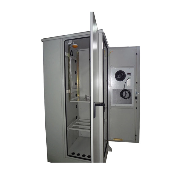
A cable management rack is designed to route, protect, and organize copper and fiber cables inside network cabinets. Beyond keeping cables tidy, a well-structured cable manager reduces cable stress, improves heat dissipation, and ensures bend-radius compliance for data transmission. This article provides a clear technical view of cable management racks, their structures, and how to select the right solution for modern networks. Cable management in server racks simply refers to organizing, routing, and securing power and data cables so they stay neat, accessible, and. Simply put, a cable rack is a structured set of shelves designed to organize, protect, and manage cables in various settings. These racks range from simple, affordable options to complex, high-capacity models that accommodate a vast number of cables. The benefits of using cable racks are numerous. Horizontal cable management is a cornerstone of efficient IT infrastructure, ensuring that server racks and enclosures remain organized, accessible, and functional., Ethernet, fiber optic, coaxial). At its core, it aims to: Minimize cable tangling, kinking, and wear. Simplify troubleshooting and maintenance. As businesses increasingly rely on robust network infrastructure, proper cable organization becomes critical for.
[PDF]
A distribution box is used to receive electrical power from a main supply and distribute it to multiple branch circuits in a safe and controlled way. It helps protect circuits, organize electrical connections, and improve maintenance efficiency. Distribution. Distribution boxes are commonly used in residential and commercial electrical systems. To learn more about distribution boxes and how they work, keep. A distribution box is a vital piece of equipment that ensures the effective and safe distribution of electrical power in various parts within a building or complex. Today, electrical systems are essential for homes and industries. It acts like a hub or traffic controller, managing power flow to different areas or devices. Key components include circuit breakers, fuses, bus bars, and internal wiring for safety and. This ultimate guide explains what a distribution box does, its internal components, common types, real-world applications, and how to select the right DB Box for your project. We also highlight how reliable manufacturers like NUOMAK support stable, compliant, and cost-effective power distribution.
[PDF]

In this article, we will explore the specifications for household distribution boxes and provide guidance on how to install them correctly. Whether you're an electrician or a DIY enthusiast, this guide will help you understand the basics of home electrical distribution. more Welcome to our. A distribution box is the heart of any electrical system. It takes the incoming power and safely distributes it to different circuits throughout your building. While many families are familiar with these boxes, there is often a lack of understanding regarding their specifications and proper. Strictly speaking, the word “Distribution Box (D-box)” can refer to two categories: electrical distribution boxes and septic tank distribution boxes. This article mainly talks about the first one. An electrical distribution box, also known as a power distribution box, panelboard, or consumer unit. Electrical wiring powers everything in your home, from lights and outlets to major appliances. Whether you're building new or updating an older system, the way your wiring is planned and installed affects how safely and efficiently everything runs. We'll break down the key parts of a home. This article is going to be very helpful for you, if you want to learn about how appliances, Motors, Generators, Light bulbs, circuit breakers, float switch, and Contactors are wired up.
[PDF]

An Optical Splitter (also known as a fiber optic splitter or beam splitter) is a passive optical power management device. “Passive” means it needs no electricity. It requires no power source to work. Imagine a water pipe. One large pipe brings water into a building. Then, smaller pipes split that. A Passive Optical Network (PON) is a fiber-optic access network designed to deliver broadband services. This technology uses fiber cable and unpowered optical components to distribute signals from a central source to multiple end-users. The “passive” designation means the signal distribution points. Optical splitters play an important role in FTTH PON networks where a single optical input is split into multiple output, thus allowing a single PON interface to be shared among many subscribers. The optical splitters have no active electronics and don't require any power to operate. Passive refers to the unpowered condition of the fiber and splitting/combining components. Together, they form the complete infrastructure that makes modern data transmission.
[PDF]
An optical transceiver module, often simply called an optical module, acts as a signal conversion interface in fiber optic networks. It transforms high volumes of electrical signals into optical signals for transmission over fiber cables, or reverses the process at the receiving. As an essential component of optical fiber communication, optical modules are optoelectronic devices that facilitate the conversion between optical and electrical signals during the transmission process. Operating at the physical layer of the OSI model, optical modules are core devices in optical. An optical module is a typically hot-pluggable optical transceiver used in high-bandwidth data communications applications. Its primary function is to achieve optoelectronic conversion by converting electrical signals into optical signals and vice versa. If you're dealing with data centers, telecommunications, or AI networking, grasping the key parameters of an optical. What is an Optical Module? The Ultimate Guide to Principles, Types, and Troubleshooting Optical Modules (also known as Optical Transceivers) are critical components in fiber optic communication systems. Among various optical module form factors, SFP (Small Form-Factor Pluggable).
[PDF]

Mechanical Optical Switches: Switching times typically range from 1-10ms, suitable for long-distance transmission scenarios where latency is not critical (such as backbone network protection switching). Solid-State Optical Switches: Based on thermooptic or electrooptic effects, response. We lead the industry in optical switch technology, delivering the lowest insertion loss (0. 2 dB), fastest switching speed (10 ns), broadest wavelength range (300–2400 nm), widest fiber compatibility, highest optical power handling (50 W), and space-qualified reliability. Backed by over 25 years of. Use this optical switches buying guide to compare major types, define selection criteria, and find suppliers: Professional purchasing of high-value photonics products is a substantial responsibility, where a structured decision-making process is essential. RP Photonics offers a lot of help: Get. This document is a troubleshooting and selection guide for common optical switch failures, compiled based on over 500 field cases. These switches are built on proven, reliable optomechanical technology that has seen more than 30 years of successful operation. Each. The POLATIS ® Series 7000 384x384 all-optical circuit switch is designed to meet the most demanding applications with exceptionally low optical loss, compact size, and fast switching speeds. With support for Software-Defined Networks (SDNs) via embedded NETCONF and RESTCONF control interfaces, the.
[PDF]

When working with laser light, a plate or cube beamsplitter offers the best combination of optical performance and power handling. a beamsplitter is choosing the right coating. Beamsplitters are optical components used to split incident light at a designated ratio into two separate beams. Additionally, beamsplitters can be used in reverse to combine two different beams into a single one. Beamsplitters are often classified according to their construction: cube or plate. A beamsplitter is an optic that splits light into 2 directions. The split ratio of light transmittance and reflectance is 1:1 and is called a half mirror. Good fit for large beam size applications at a reasonable price. This precise ability to direct light paths makes beam splitters essential in various applications, including imaging systems, laser. Plate beamsplitters are made using a coated substrate, and thus exhibit beam offset and ghost reflections from the second surface. Cube beamsplitters avoid beam displacement by working at 0° angle of incidence and placing the coated surface between two right angle prisms, but power handling can be. This Beamsplitters Selection Guide outlines the core types of beamsplitters, explains how they work, and provides practical advice for choosing the best one for your application. Newport offers a wide variety of Beamsplitters in various shapes.
[PDF]

It is a technique that uses controlled heat to permanently fuse two optical fiber ends together. Unlike mechanical splicing, which relies on alignment sleeves and index-matching gel, this thermal approach creates a continuous glass path between fibers. Optical fiber transmission has the advantages of wide transmission frequency, large communication capacity, low loss, no electromagnetic interference, small diameter of optical cable, light weight, rich source of raw materials, etc., so it is becoming a new transmission medium. When light is. Common splicing methods include optical fiber cold splicing and optical cable hot fusion splicing. Advantages and disadvantages of fiber optic cold splicing Fiber cold splicing refers to using special tools to mechanically connect two optical fibers. Its advantages include: Simple operation and. This is part 6 of a tutorial on passive fiber optics from Dr. The tutorial has the following parts: Optical fibers can be joined together, such that light is efficiently transferred from one fiber to another. There are various possibilities: Mechanical splicing means that two fiber ends. This guide reveals the secrets to fusion splicing with little fluff—just proven, straightforward techniques refined from years of work in the field. The result is a joint that closely matches the.
[PDF]

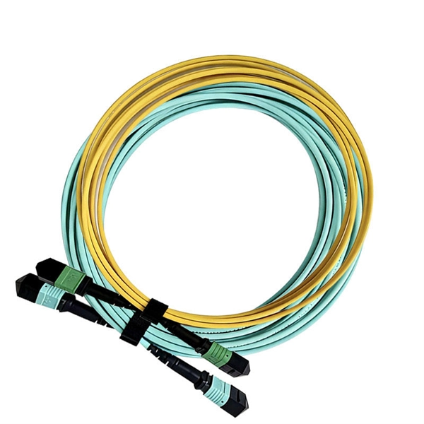
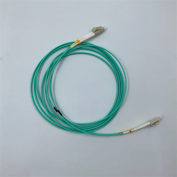
This comprehensive guide will delve into the most effective practices, key considerations, and strategic approaches for designing and implementing an efficient cabling system within a data center environment. At the core of data center connectivity are fiber optic cables, which are thin strands of plastic that transmit data using light signals or wavelengths, offering unparalleled speed and efficiency. The data superhighway paved by fiber optics forms the backbone of modern data centers, ensuring rapid. An end-to-end cabling system is an ideal solution for data centers especially when time for traditional cable installation and termination is limited. Explore advanced configurations, testing protocols, and industry best practices. As the demand for data surges, these switches become more vital in sustaining networks that are efficient, scalable, and. As data centers continue to grow in complexity and scale, efficient fiber optic cabling is essential for maintaining high performance, reliability, and scalability. Proper planning and implementation of cabling infrastructure can significantly reduce downtime, improve airflow, and ensure. center hardware layout design. This map should include the cabinet placements, patch panels, hardware, port-counts, trunking locations and power access connection points. Future plans for change will be discussed, as well as the bandwidth required. infrastructure design. The design's intent is to.
[PDF]

This article will give you an overview of the use cases for fiber-optic networking, some of the terms used in fiber networking, and suggestions for setting up a fiber network. Once you understand the basic concepts, you can check out my Recommended Equipment section toward. Fiber tapping is a network tap method that extracts signal from an optical fiber without breaking the connection. Tapping of optical fiber entails diverting some of the signal being transmitted in the core of the fiber into another fiber or a detector. Fiber to the home (FTTH) systems use beam. Optical fiber is a technology used to transmit data by sending short light pulses along a long fiber, which is typically made of glass or plastic. In optical fiber communication, metal wires are preferred for transmission because the signals travel more safely. Optical fibers are also resistant to. Photo: Light pipe: fiber optics means sending light beams down thin strands of plastic or glass by making them bounce repeatedly off the walls. This is a simulated image. Note that in some countries, including the UK, fiber optics is spelled "fibre optics. " If you're looking for information online. This manual covers everything about fiber optic cables, how they work, where they are used, and what is new in this area of technology. The choice of fiber optic cable depends on the specific needs of the application, as well as the.
[PDF]