
Welcome to our channel! In this video, we'll walk you through the process of wiring a home distribution box with a detailed connection diagram. What is Distribution Board? Distribution board. These smaller breaker panels, also known as sub-distribution boards, are commonly used to provide power to secondary circuits within a building. Understanding the components and wiring configuration of an electrical sub panel is essential for safe and efficient electrical installations. In this. Primary distribution systems consist of feeders that deliver power from distribution substations to distribution transformers. A feeder usually begins with a feeder breaker at the distribution substation. Many feeders leave substation in a concrete ducts and are routed to a nearby pole. This breaker must be compatible with both your main system and the additional connections. Typically, a 60-amp or 100-amp breaker will be suitable, depending on the load requirements. It includes isolator, RCCB (Residual current circuit breaker) or RCD (Residual-current device) devices, protective fuses or MCB's (Miniature Circuit Breaker).
[PDF]

The Cisco Catalyst 9200 Series switches have modular (C9200) and fixed (C9200L) switch models. Huijue Group's Mobile Solar Container offers a compact, transportable solar power system with integrated panels, battery storage, and smart management, providing reliable clean energy for off-grid, emergency, and remote site applications. As a professional manufacturer in China, produces both. Base station energy cabinet: a highly integrated and intelligent hybrid power system that combines multi-input power modules (photovoltaic, wind energy, rectifier modules), monitoring units, power distribution units, lithium batteries, smart switches, FSU and ODF wiring, etc. Stackable 24x1G PoE+ ports; 4x1G SFP fixed. With global energy storage deployments projected to reach 387 GWh by 2030, proper installation of energy storage cabinets has become mission-critical. But why do 43% of commercial installations still experience thermal management failures within the first year? Let's decode the technical nuances. Huijue Group's energy storage solutions (30 kWh to 30 MWh) cover cost management, backup power, and microgrids., to effectively solve.
[PDF]

This document discusses the implementation for Cisco Software-Defined Access (SD-Access) deployments for Airports. For the associated deployment guides, design guides, and white papers, refer to the following documents:. The low noise Silent Switcher architecture simplifies design and PCB layout to help streamline development and reduce the chance of a redesign. The compact Silent Switcher solution size supports a range of applications, including industrial, instrumentation and measurement, healthcare, aerospace. AIRPORT ELECTRICAL DESIGN STANDARDS Los Angeles World Airports 1. 1 GOALS The goal of this section is to provide guidance for all electrical work at LAWA. Additional discipline specific guidance related to electrical work can be found throughout the Design & Construction Handbook (DCH). This page provides a quick reference to engineering, design, and construction standards for various airport-related equipment, facilities, and structures. Visit our Series 150 Advisory Circular Library for a complete listing of current advisory circulars. Simpleway's battle-tested hardware ecosystem combines nnounce audio devices with digital signage controllers, creating a unified communication infrastructure built from real airport experience - from routine gate operations to full-terminal evacuations. Discover how nnounce devices create a.
[PDF]
We connect the client to the fiber optic network, configure connection parameters and provide technical support. Our vision is to be the leading provider of fiber optic solutions and services in Norway. When we were established in 2001, we were among the first companies in Norway to specialize in fiber optics. This has. Trust us, we know fiber optics. We are an industry leader and have over 10 years of experience in installing and operating fiber optic networks. We analyze the client's needs, select optimal technical solutions and prepare design documentation. In this comprehensive guide, we'll explore the best fiber optic installation companies, focusing on their capabilities, product ranges, and the unique benefits they offer in fiber optic cabling and installation. If you're ready.
[PDF]

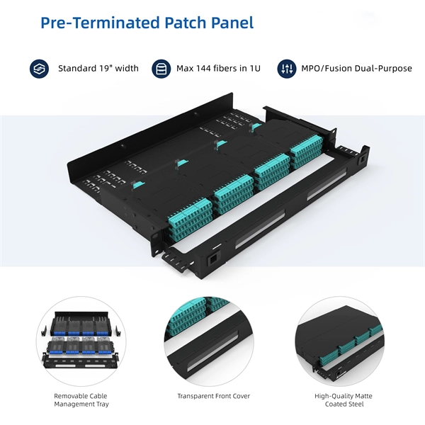
This document provides direction on properly identifying the ribbon and individual fiber in the AFL Wrapping Tube Cable. Depending on fiber-count, ribbon band-marking (striping) and binder group count will differ. The number of optical cores in an optical fiber is the total number of equipment interfaces multiplied by 2, plus 10% to 20% of the spare quantity, and if the communication mode of the equipment has serial communication and equipment multiplexing, you can reduce the number of cores. The number of. A fiber optic patch panel is a critical piece of equipment used to organize, manage, and connect fiber optic cables within a network. It serves as a central hub where multiple fiber optic cables can be routed, terminated, and interconnected to various network devices such as switches, servers, or. Fiber optic cables are essential to modern networks, enabling high-speed and reliable data transmission. Among their many features, the number of fiber cores directly affects data capacity and network performance. Understanding this key aspect is crucial for making the right choice. This post will guide you through understanding fiber optic cores and selecting the perfect cable for.
[PDF]

This AutoCAD DWG file includes a complete Single Line Diagram (SLD) of a Distribution Board, showing circuit breakers, wiring connections, and load distribution for lighting, power, and mechanical systems. Distribution box The system diagram usually shows the electrical connection and configuration inside the distribution box in a graphical way, including busbars, circuit breakers, fuses, load devices and other elements. In practical applications, the corresponding system diagram can be drawn. An Electrical Distribution Board (DB) is an essential component of any electrical system — it receives power from the Main Distribution Board (MDB) and distributes it to various sub-circuits or equipment. Power supply is received from LT panel and distributed to the outgoing feeders for utilization. Understand its role in electrical systems and safety. Inside. The distribution box (DB box) helps safely and efficiently distribute electrical power. But what exactly is a power distribution box, and why is it so essential in our daily lives? The DB panel board controls the flow of electricity. Wiring diagram shows both PNP and NPN wiring. Actual units use PNP status indicator, NPN status indicator, or neither. Dimensions are shown in mm (in. 40 ft)] or 10 [10 m (32.
[PDF]

In this guide, you will find a chronological description of the fusion splicing process, the principal technical standards, and answers to the real-life questions network engineers and procurement teams may have. In this guide, we cover the basics of fiber optic splicing, how to perform splicing using two different methods, and finally some best practices to perform good fiber splicing. What is Fiber Optic Splicing and Why is it Needed? – #1. Use and Maintain Your. This Geoschematics drawing remains easy to read despite containing more than 2000 fibers and 500 splices. Splice Diagrams or Matrices capture an electric or optical network inside a location – documenting cables, ported equipment, and connections. Splices are fiber-to-fiber, port-to-fiber and. This guide will walk you through the complete process of fiber optic splicing—covering each step in detail so you can deliver a clean, professional splice every time. Before jumping into the physical steps, it's important to understand the two primary methods of fiber splicing: fusion splicing and. Page 1 The FOSC 450 fiber optic splice closures use compressed-gel cable seals to environmentally seal fiber cable splice points. FOSC 450-ab-c-dd-e-fgh The maximum single splice capacity of the FOSC 450 B6 closure is a = Closure size 144 with 24 splices stored on six trays. Therefore, we will also touch on cost factors, risk management, and best practices in.
[PDF]

Fiber optic network diagrams represent the architecture and connectivity of fiber optic systems, and their design philosophy integrates technical, functional, and conceptual aspects. The diagrams abstract complex details of fiber optic systems to make them understandable for. Fiber optic network design refers to the specialized processes leading to a successful installation and operation of a fiber optic network. It includes first determining the type of communication system (s) which will be carried over the network, the geographic layout (premises, campus, outside. A fiber optics network diagram illustrates how high-speed data travels from an internet service provider to end users. These diagrams help engineers plan infrastructure for residential and commercial buildings. It includes detailed mapping of backbone, distribution, and drop connections for FTTH, FTTP, FTTx, and enterprise networks. Planning and design is a process that includes many decisions, involving first defining the communication protocols to be used on the network and defining geographical layout. It also involves selecting transmission equipment.
[PDF]
We are a one-stop shop for top-notch Electrical Cable Tray in Moldova. Our cable trays are manufactured from robust materials and rigorously tested to ensure they can withstand even the most demanding environments. We, one of the top Electrical Cable Tray Manufacturers in Moldova, offer a wide. Looking for a trusted source to buy Cable Tray In Moldova? Brilltech Engineers Pvt. Ltd is the one you can reach. We have a highly experienced team, well-loaded manufacturing unit and a lot more to match up the ever-evolving needs of our customers. Moreover, our focus on maintaining high quality. Jeetmull Jaichandlall (P) Ltd. We believe in building fruitful business partnerships. Every buyer chooses us first because of our excellent finishing and. Cable House has earned loads of appreciation in the market as one of the reputed manufacturers of Cable Tray in Moldova. Being one of the leading Cable. Fire safety and fire resistance are vital part of responsible electrical designing and installation. Meka Pro has tested and continues to test its products and cable management systems´ fire resistance with the cables installed and connected according to the temperature curve in the EN 1363-1.
[PDF]

When laying loops of fiber on a surface during a pull, use “ figure-8 ” loops to prevent twisting the cable. Bending of a fiber optic cable can damage the cable if the radius of the bend is too small. However there are some general rules that should be. If the cable remains outside for more than 24h during installation protective material should be used to prevent cable damage. The maximum installation and storage temperatures specified for each cable in the data sheet must be respected. The specified values apply to the cable temperature and not. Tension on the cable and pulling ropes can cause twisting. Use a swivel pulling eye to connect the pull rope to the cable to prevent pulling tension causing twisting forces on the cable. Roll the cable off the spool instead of spinning it off the spool end to prevent putting a twist in the cable. The device prevents the cable from twisting as it travels over pulling blocks. Left uncontrolled, the optical cable's delicate glass fibers could be permanently damaged during installation. We do so appreciate your efforts. It happens during installation, when excessive pulling force, tight bends. Fiber optic cable bend radius is a critical mechanical parameter that determines how sharply a cable can be bent without risking microbending, macrobending, signal loss, or long-term structural fatigue. Proper bend radius control ensures the integrity of optical performance and protects the glass.
[PDF]

This guide covers the critical steps, from selecting the right electrical cable tray and performing accurate cable fill calculations to managing a safe cable pull through and ensuring all bonding and grounding requirements are met. Cable tray installation implies the construction of an electric road that will be safe. In order to get it right, installers are supposed to adhere to a plan that ensures that wires are kept cool and the building is stable. The beginning of success is to review the Bill of Quantities (BOQ) so that. Whether you're building a commercial setup or upgrading an industrial plant, proper cable tray installation ensures neat wiring, safe access, and easy maintenance. But before you lay the first tray or clamp down a single cable, you need a solid plan. This guide breaks down the process step by step. Whether you're an experienced electrician or a DIY enthusiast, this video is perfect for you. more. Installing a cable tray system requires careful planning to ensure it can support the weight of the cables and adheres to electrical safety codes. Here is a step-by-step guide on how to install a standard metal cable tray system (e., ladder or perforated type). Before starting, ensure you have. Proper installation of cables in trays is critical for maintaining an efficient and safe electrical system. This is why proper planning and execution are.
[PDF]

The following recommendations are intended to be a practical guide to ensure the safe and proper installation of cable ladder and cable tray systems and channel support and other support systems. Swifts cable ladder has been tried and tested in installations of all sizes, around the world, from medium duty requirements in small, commercial buildings through to extra heavy duty installations in refineries, logistics centres and heavy industry applications. This new wide span offer in PG. This method statement covers the site installation of the cable tray & ladders and the requirements of checks to be carried out. The Cable Tray system is installed in electrical rooms, plant rooms, and service corridors. This section will guide you through the necessary steps to ensure a successful. Cable trays type: Light, Medium & Heavy duty. Materials: Pre Galvanized steel. Looking for a trusted source to buy Ladder Cable Tray In Tanzania? Brilltech Engineers Pvt. Ltd is the one you can reach. We have a highly experienced team, well-loaded manufacturing unit and a lot more to match up the ever-evolving needs of our customers. These products are manufactured using high-quality materials such as galvanized steel, which provides resistance to corrosion and ensures durability in harsh environments. Features: All Rights Resevered 2024. Volex Electrical Engineering Limited.
[PDF]

Searching IndustryNet for cable tray suppliers, servicing Georgia (GA). Get Free Quotes & Information from these Companies (No Obligation - Click Here!). American Tech Supply a division of American Data provides a complete end cable tray, basket tray and Raceway System solution. Cable Tray and Cable ladder along with wire mesh trays are cable support systems that run large quantities of power or data cable overhead or under floors. Made from aluminum, pre-galvanized wiring and stainless steel, carbon steel or mild steel materials. Available in up to 1/16 in. Capabilities include. Our cable routing systems are easy to install and can be extended. Our broad range of standard cable trays are particular well-suited for cabling in buildings. Cable trays with a lock allow fast cable installation and exchange. We are a custom manufacturer and a service provider in wire & metal bending, forming, threading, stamping and piercing. Serving multiple industries for their wire & cable needs. Products: Trays or. In 1996, Roger Jette saw how fabricating generic cable trays slowed down the entire project so he had an idea to create a hand bendable cable tray to substantially lower construction costs and installations times. Twenty nine years and over 30 patents later, Snake Tray is the market leader.
[PDF]
