
A cold aisle is a cooling strategy where the fronts of server racks face each other, creating a dedicated pathway for cool air from the cooling systems to flow directly into the equipment. This configuration minimizes the mixing of hot and cold air, ensuring consistent airflow and. The hot aisle /cold aisle data center layout was originated by IBM in 1992 and it is one of the oldest ways to save energy in the data center. Cold. Hot aisle and cold aisle containment are foundational concepts in data center design. When implemented correctly, they improve efficiency, reduce energy consumption, extend equipment life, and enhance overall reliability. In this guide, we'll break down how hot aisle and cold aisle configurations. The segmentation of data centers and server rooms into alternating cold and hot aisles has been embraced globally over recent years. The cold and hot aisle arrangements in data centers are part of an energy-conservative layout for server racks and other information technology equipment. Containment. Why should the computer room design hot and cold aisles, design principles and how to construct? Why should the computer room design hot and cold aisles? Because the computer room uses the hot aisle and cold aisle to change the previous practice of placing the cabinets in the same direction in the. Hot and cold aisle containment is a proven strategy to optimize airflow, reduce energy costs, and improve cooling efficiency. Whether you need cold aisle.
[PDF]

A fiber optic adapter (or fiber coupler) is a passive component used to join and align two optical connectors. It plays a key role in maintaining core-to-core alignment, allowing optical signals to pass through with minimal insertion loss and stable performance. Fiber optic adapters play a critical role in ensuring stable and low-loss fiber connections. This guide covers adapter types, selection criteria, cleaning tips, FAQs, and B2B customization options to help businesses build reliable and scalable fiber networks. They enable seamless and reliable optical signal transmission between different fiber optic cables, connectors, or devices., two fiber connectors) such that light can reliably pass from one to the other with minimal insertion loss and maximum return loss. A fiber-optic adapter connects two optical fiber connectors in the fiber optic lines. Bare fiber adapter is used as the medium to temporarily link the bare optical fiber to fiber optic equipment. Available with FC, SC, ST. LC, MU, SMA connectors with round or square type press button. This article discusses their purposes, features, types, and how to choose and clean them. What is a Fiber Optic Adapter?.
[PDF]

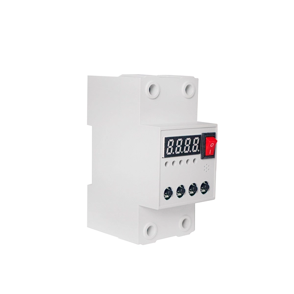
Primary: The main distribution panel, supplies power from the transformer. The terms primary, secondary, and tertiary distribution boxes are relative. Let's make an example for clarity: A newly constructed residential area introduces a 10kV power line to a substation. From the transformer's low-voltage side (0. Spot Networks are used for customers with the highest reliability requirements. This configuration connects two or more transformers (fed from at least two. A complete set of products can form a complete construction electricity three-level protection system, to achieve the purpose of one machine, one gate, one protection. The secondary box is designed with inside and outside doors and sprayed with plastic. Safe and beautiful, waterproof box top. These smaller breaker panels, also known as sub-distribution boards, are commonly used to provide power to secondary circuits within a building. Understanding the components and wiring configuration of an electrical sub panel is essential for safe and efficient electrical installations. In this. ACS takes the basic idea of zone wiring and combines it with pre-cut, pre-tested cable and plug-in connectors, to provide power and telecommunication systems that can be installed under raised floors (The Intelligent Floor), or in accessible ceilings (The Intelligent Ceiling). installed under.
[PDF]

This instrument enables high speed measurement of the optical properties of LD and LED light sources, optical amps, and other devices. To improve ease of use, it includes mouse-based user operation and a brand-new zoom function. If you want to resolve a technical support issue or need to contact YOKOGAWA, please fill out the inquiry form on our website. Thank you for purchasing the AQ6370D Optical Spectrum Analyzer. T o ensure correct use, please read this manual thoroughly before beginning operation. a question arises during operation. In addition to this manual, there is one individual manual each for the. The Yokogawa AQ6370D series optical spectrum analyzer is a high-performance and multifunctional testing instrument widely used in various fields such as optical communication, laser characteristic analysis, fiber amplifier testing, and WDM system analysis. This remote control user's manual covers the AQ6370C, AQ6370D, AQ6373, AQ6373B, AQ6375 and AQ6375B. YOKOGAWA provides registered users with a variety of information and services.
[PDF]
Optical cable junction boxes play a crucial role in connecting and protecting optical fibers, directly influencing the quality and lifespan of optical cable routes. Optical cable splice boxes protect the splicing parts of optical fibers from various hazards, such as water seepage due to adverse. Optical cable junction boxes play a crucial role in managing and organizing fiber optic networks. It serves as a termination point for fiber optic cables, providing protection and distribution of the optical fibers while ensuring efficient signal transmission. Utilizing an optical junction box can significantly enhance your. Optical cable splice box is a popular name, its scientific name is optical cable splicing box, also known as optical cable splicing package, optical cable splicing package and gun barrel. These boxes are designed to house and protect fiber optic splices and terminations, ensuring that the delicate fibers are safeguarded from.
[PDF]

SFP optical module is a hot swappable optical module used for 1Gbps network connections. It has a small size and can be plugged into the optical interface of the server, providing connections for fiber and copper cables. That is, metal medium communication represented by coaxial cables and network cables is gradually being replaced by optical fiber media. Composition of Optical Modules The optical module, known as Optical Transceiver in. The Transmitter Optical Sub Assembly (TOSA) is responsible for the emission of light. Its primary function entails converting electrical signals into optical signals. SFP modules are mainly used for short distance fiber optic connections, such. As an essential component of optical fiber communication, optical modules are optoelectronic devices that facilitate the conversion between optical and electrical signals during the transmission process. They are used in fiber optic communication systems to transmit data over long distances with minimal loss and interference. These modules typically consist of a laser or LED transmitter, a. Optical modules can bridge different network components while transmitting and receiving data, ensuring smooth information flow.
[PDF]

Busbars operate as conductive bars that distribute electricity from incoming feeders to outgoing circuits within an electrical system. By providing a low-resistance path, busbars ensure efficient current distribution with minimal power loss. These components are typically mounted within an. Electrical busbars are solid conductors used to carry and distribute high current in switchgear, panels, substations, and power systems. This guide explains how busbars work, common types, key design factors, and how to choose the right busbar for your application. An electrical busbar is a solid. The busbar electrical system performs several essential functions that support efficient power management: Power Distribution: It is a central station to which the electrical power is brought out of one source and to more than one circuit. Existing Transmission: Electric busbar transmits huge. I. Basic Definition of the Small Busbar at the Top of the High-Voltage Cabinet The small busbar at the top of the high-voltage cabinet, as the name suggests, is a small busbar device installed at the top of the high-voltage switchgear. Its primary role is to carry large current loads and connect multiple circuits together. Think. An electrical busbar functions as a metallic conductor, playing a pivotal role as a central link for multiple electrical connections. These connectors can take on various forms including solid, hollow, or even flexible designs to suit different needs.
[PDF]
The aluminium alloy joint box are applicable for connection protection of special optical cables,with the functions of direct and branch connection, with the maximum of 6 optical cables, which mainly for overhead rods and towers. Explore top-quality OPGW hardware fittings, setting a new standard for secure and efficient connections in our Pole Line Hardware. The joint box is made of aluminium alloy and has a maximum capacity of 192 fibre splices. A pre-moulded neoprene anti-aging gasket. No. 77, East District, Sixian Industrial Zone, West Ring Road Office, Renqiu City,. An assembling plate trays is placed inside the box. Cable glands and a heavy wall OPGW cables. The anchoring of the joint box to the tower is poles. It features in high mechanical strength, good airtight and anti-corrosive. Having been sealed with sealing ring and silicone, it could be opened, expansed, fixed, and connected repeatedly. It's suitable in aerial. Optical cable junction boxes play a crucial role in connecting and protecting optical fibers, directly influencing the quality and lifespan of optical cable routes. Optical cable splice boxes protect the splicing parts of optical fibers from various hazards, such as water seepage due to adverse.
[PDF]

Beam splitters are classified by construction (plate, cube, pellicle, polka dot) and by function (standard, non-polarizing, polarizing, dichroic). Construction determines ghosting, damage threshold, and form factor. Function determines how polarization and wavelength are. Beamsplitters are optical components used to split incident light at a designated ratio into two separate beams. Additionally, beamsplitters can be used in reverse to combine two different beams into a single one. Beamsplitters are often classified according to their construction: cube or plate. A beam splitter or beamsplitter is an optical device that splits a beam of light into a transmitted and a reflected beam. It is a crucial part of many optical experimental and measurement systems, such as interferometers, also finding widespread application in fibre optic telecommunications. This division allows for the simultaneous analysis or utilization of the light's properties along two separate paths. These versatile tools can split both laser and regular light, depending on the application in question. Its fundamental purpose is to precisely control the path and intensity of light, making it a ubiquitous component across various optical systems. For a lossless beam splitter, R + T = 1. When comparing beam splitters, always check whether the specified R/T ratio is for unpolarized light or for a specific polarization. The numbers can differ.
[PDF]

An elevator data communication system is configured to communicate between a plurality of elevator systems and a datacenter remotely located from the plurality of elevator systems. WAN – Wide area network is similar to a LAN but is not limited to a single location. It can also consist of several LANs which are interconnected. Usually, it is the only way how to contact the outside world and get help when you are trapped in the elevator. But many changes and exciting new challenges are coming in the field of elevator. “THE LONGEST RUNNING PUBLICATION FOR THE VERTICAL TRANSPORTATION INDUSTRY SINCE 1953. ” Open and standard communication protocols are vital for interoperability in building automation and elevators. The OSI seven-layer model frames protocol design but compliance alone does not guarantee. Elevators are essential in most modern buildings, but they need communication systems that meet code requirements. Here's how new features are making compliance easier—and delivering a new revenue stream. More sophisticated and effective communication solutions are needed to manage the increasing. Technical systems are, in general, becoming ever more complex. Electronic systems – usually equipped with tiny embedded microprocessors – are implementing new functions, increasing convenience or improving system safety and reliability.
[PDF]
An optical power meter (OPM) is a device used to measure the power in an signal. The term usually refers to a device for testing average power in systems. Other general purpose light power measuring devices are usually called,, power meters (can be sensors or ), or lux meters. A typical optical power meter consists of a , measuring and display. The sens.
[PDF]
Energy Internet refers to a combination of advanced power and electronics technology, information technology and intelligent management technology, and a large number of new power networks, petroleum networks, natural gas networks, etc., which are composed of distributed energy gathering devices. The so-called 'low-altitude economy' - encompassing drones, electric vertical takeoff and landing aircraft (eVTOLs), airborne data platforms and the infrastructure that supports them - is poised to become a pillar of China's next develo. read more Kanpai! Space-brewed sake sells for $700,000.
[PDF]
Due to combinations of intense securitization, Western sanctions, foreign businesses exiting Russia, tech “brain drain,” and other factors, digital technological isolationism is now both a reality and a desired goal for Moscow. Digital technology has long been a key component of the Russian government's power, and for years following the collapse of the Soviet Union there was significant technology entanglement between Russia, the West, and other areas of the world. That changed in the late 2000s and early 2010s with. ANDREI SOLDATOV is a Nonresident Senior Fellow at the Center for European Policy Analysis and Co-Founder and Editor of Agentura. ru, a watchdog of the Russian secret services' activities. However, another set of players has a key role in the Russian cyber ecosystem: private sector. What's Next for Japanese Security Policy and U. -Japan Relations? Perspectives from the Diet The principal goals driving Russia's cyber strategy across the spectrum of conflict are clear: disruption, destruction, and control of information. Its cyber governance is centralised, hierarchi-cal and under the president's personal control. The country is highly dependent on foreign.
[PDF]


