
This AutoCAD DWG file includes a complete Single Line Diagram (SLD) of a Distribution Board, showing circuit breakers, wiring connections, and load distribution for lighting, power, and mechanical systems. Distribution box The system diagram usually shows the electrical connection and configuration inside the distribution box in a graphical way, including busbars, circuit breakers, fuses, load devices and other elements. In practical applications, the corresponding system diagram can be drawn. An Electrical Distribution Board (DB) is an essential component of any electrical system — it receives power from the Main Distribution Board (MDB) and distributes it to various sub-circuits or equipment. Power supply is received from LT panel and distributed to the outgoing feeders for utilization. Understand its role in electrical systems and safety. Inside. The distribution box (DB box) helps safely and efficiently distribute electrical power. But what exactly is a power distribution box, and why is it so essential in our daily lives? The DB panel board controls the flow of electricity. Wiring diagram shows both PNP and NPN wiring. Actual units use PNP status indicator, NPN status indicator, or neither. Dimensions are shown in mm (in. 40 ft)] or 10 [10 m (32.
[PDF]

This document provides direction on properly identifying the ribbon and individual fiber in the AFL Wrapping Tube Cable. Depending on fiber-count, ribbon band-marking (striping) and binder group count will differ. The number of optical cores in an optical fiber is the total number of equipment interfaces multiplied by 2, plus 10% to 20% of the spare quantity, and if the communication mode of the equipment has serial communication and equipment multiplexing, you can reduce the number of cores. The number of. A fiber optic patch panel is a critical piece of equipment used to organize, manage, and connect fiber optic cables within a network. It serves as a central hub where multiple fiber optic cables can be routed, terminated, and interconnected to various network devices such as switches, servers, or. Fiber optic cables are essential to modern networks, enabling high-speed and reliable data transmission. Among their many features, the number of fiber cores directly affects data capacity and network performance. Understanding this key aspect is crucial for making the right choice. This post will guide you through understanding fiber optic cores and selecting the perfect cable for.
[PDF]

Fiber optic network diagrams represent the architecture and connectivity of fiber optic systems, and their design philosophy integrates technical, functional, and conceptual aspects. The diagrams abstract complex details of fiber optic systems to make them understandable for. Fiber optic network design refers to the specialized processes leading to a successful installation and operation of a fiber optic network. It includes first determining the type of communication system (s) which will be carried over the network, the geographic layout (premises, campus, outside. A fiber optics network diagram illustrates how high-speed data travels from an internet service provider to end users. These diagrams help engineers plan infrastructure for residential and commercial buildings. It includes detailed mapping of backbone, distribution, and drop connections for FTTH, FTTP, FTTx, and enterprise networks. Planning and design is a process that includes many decisions, involving first defining the communication protocols to be used on the network and defining geographical layout. It also involves selecting transmission equipment.
[PDF]
The procedures of testing switchgear, instrument transformers and relays are explained in detail. The close and trip, indication and alarm circuits for variety of circuit breakers indicating ferrule numbers are al.
[PDF]

Welcome to our channel! In this video, we'll walk you through the process of wiring a home distribution box with a detailed connection diagram. What is Distribution Board? Distribution board. These smaller breaker panels, also known as sub-distribution boards, are commonly used to provide power to secondary circuits within a building. Understanding the components and wiring configuration of an electrical sub panel is essential for safe and efficient electrical installations. In this. Primary distribution systems consist of feeders that deliver power from distribution substations to distribution transformers. A feeder usually begins with a feeder breaker at the distribution substation. Many feeders leave substation in a concrete ducts and are routed to a nearby pole. This breaker must be compatible with both your main system and the additional connections. Typically, a 60-amp or 100-amp breaker will be suitable, depending on the load requirements. It includes isolator, RCCB (Residual current circuit breaker) or RCD (Residual-current device) devices, protective fuses or MCB's (Miniature Circuit Breaker).
[PDF]
Ask This Old House master electrician Heath Eastman explains the uses and purposes of different types of electrical boxes. Selecting the right electrical box for your project can be confusing because of the many options available. Circuit breaker boxes – also known as breaker panels or main breaker panels – keep the lights on, electronic devices powered up and the refrigerator running. They host circuit breakers designed to safely distribute the correct amount of electricity to every room and outlet in your home. Whether you're starting new construction or adding to existing. Electrical boxes, also known as junction boxes or outlet boxes, are enclosures that house electrical connections, switches, and outlets. Whether you're a homeowner planning a renovation or a curious mind eager to understand the backbone of modern living, our expert residential electrician insights will illuminate every twist, turn, and wire connection, ensuring your home remains both functional and safe. What is Electrical Wiring?. Electrical panel replacement costs range from $518 to $2,188, and your total reaches up to $4,500. The amperage your home needs and the type of panel you choose will determine your final project cost for the replacement. You should budget for permits, drywall repairs, and wiring upgrades so your.
[PDF]

It's called a breaker box, and even though it might not look very exciting on the outside, what's behind that little door is the heart of your home's electrical system. Bottom Line Up Front: Your home's distribution box (electrical panel) is typically located in the basement, garage, utility room, or mounted outside near your electrical meter. To find it quickly, look for a rectangular gray metal box about the size of a medicine cabinet, often positioned close to. Electrical panel boxes, aka breaker boxes, can be on a wall in an out-of-the-way area of your home. You can find electric panels inside cabinets, behind refrigerators, or inside clothes closets in older homes. Current National Electrical Codes (NEC) allow none of these locations. Electrical panels. The electrical panel is the central hub that distributes electricity throughout the house. Knowing where to find your electrical panel in your home helps in case of emergencies and routine maintenance. Panels are commonly found in garages, basements, utility rooms, and outdoor walls. Understanding how your electrical panel works can help you troubleshoot issues, perform basic maintenance, and know when to. When something electrical goes wrong in your home—like a tripped circuit or sudden power outage in one part of the house—most people instinctively head to that gray metal panel, often hidden in a basement, utility closet, or garage. Having the breaker box.
[PDF]

The main service panel is typically located in a home's basement or utility room. Some homes also have a subpanel—a smaller version of the main panel—to control electrical circuits in a garage, workshop, or other outbuilding. The National Electrical Code (NEC) does not specify a minimum height for an electrical panel, although practical access for service should always be considered. But there is a maximum height allowed for an electrical panel, which is based on the height of the highest breaker switch in the panel. NEC Article 408 covers switchboards, switchgear, and Panelboards installation and applications. Guidelines set by the National Electrical Code (NEC) provide a framework that ensures these installations adhere to stringent safety protocols. This article provides an exhaustive examination of the principles and standards governing the height at which electrical panels should be installed. The National Electric Code (NEC) includes the minimum standards for installing a circuit breaker panel box. These standards set the minimum safety standards for panel boxes. Tomorrow I'll be looking at a panel that was installed in a dining room knee wall 18" above floor. You can find electric panels inside cabinets, behind refrigerators, or inside clothes closets in older homes. Electrical panels.
[PDF]

This AutoCAD DWG file includes a complete Single Line Diagram (SLD) of a Distribution Board, showing circuit breakers, wiring connections, and load distribution for lighting, power, and mechanical systems. An electrical panel box, also known as a breaker box or a distribution board, is a crucial component of any electrical system. It serves as a central hub for distributing electricity throughout a building, ensuring that power is delivered safely and efficiently to all the required locations. Whether you're an electrician or a DIY enthusiast, this guide will help you understand the basics of home electrical distribution. What is Distribution Board? Distribution board. Welcome to our channel @Electricalgenius In this video, we'll take you through a detailed step-by-step guide on wiring a home distribution DB (Distribution Board) box. A distribution board (also known as a service panel or breaker box) is a centralized collection of circuit breakers, fuses, and/or relays used to control and protect the wiring in a home. The diagram. To understand how a breaker box works, it is helpful to have a wiring diagram that shows the connections between the various components. At the heart of a breaker box is the main breaker, which controls the flow of electricity from the utility into the building. This breaker is connected to a.
[PDF]
Engineers involved in the design, characterization and validation of Universal Serial Bus Revision 2.0 (USB 2.0) devices face pressure to speed new products to market. Tools are available to help them quickl.
[PDF]

Fiber optic network diagrams represent the architecture and connectivity of fiber optic systems, and their design philosophy integrates technical, functional, and conceptual aspects. The diagrams abstract complex details of fiber optic systems to make them. Fiber optic network design refers to the specialized processes leading to a successful installation and operation of a fiber optic network. It includes first determining the type of communication system (s) which will be carried over the network, the geographic layout (premises, campus, outside. A fiber optics network diagram illustrates how high-speed data travels from an internet service provider to end users. These diagrams help engineers plan infrastructure for residential and commercial buildings. What is fibre network mapping? Fibre network mapping is a critical process in the planning, deployment, and management of fibre optic networks. I'm needing symbols for common fiber optic components, cables, connectors, backbone ports, etc. Can anyone help me out? Some examples of a diagram would also help. 10-27-2018 01:41 AM Do you know if there's some symbol standard. Definition: Fiber optic cable is also called the “ Optical Fiber Cable “, and it is simply Ethernet networking cable that contains the multiple optic fibers, and they allow to transmit data with massive volume. Main goal of designing the optical fiber cable is to offer ultra performance data.
[PDF]

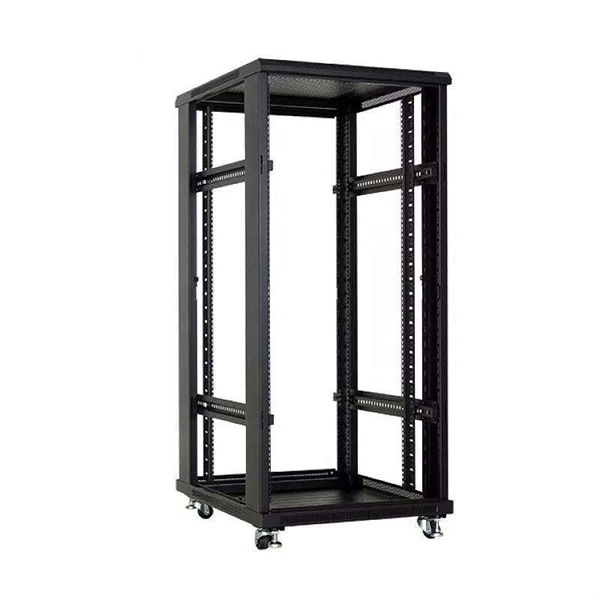
In this guide, you'll learn how to create rack diagrams that are accurate, scalable, and easy to maintain—so you can plan smarter, troubleshoot faster, and keep your infrastructure organized. This guide will explore the cost breakdown for rack and stack solutions, factors that influence pricing, and how companies can optimize their setup costs for maximum efficiency. Additionally, we will take a closer look at Digital Infotech Solutions, a leader in providing custom rack and stack. Most data center colocation providers hide pricing behind request-for-quote (RFQ) processes. You contact them, wait three to five business days, and only then learn whether colocation fits your budget. This opacity makes it nearly impossible to benchmark costs, negotiate terms, or plan. Whether you're planning a new deployment, reorganizing a rack, or documenting existing infrastructure, a clear visual layout keeps everyone aligned and prevents costly mistakes. Visit our free and simple network rack planning tool to create and export your rack. No registration or download required. Just follow this link and start designing in our pre-designed Server Rack Diagram Template. Before you. A rack diagram is a two-dimensional elevation drawing showing the organization of specific equipment on a rack. It provides a clear overview of the physical layout of the rack, including the placement and positioning of servers, switches, storage devices, and other.
[PDF]

In this video, we'll walk you through the process of wiring a home distribution box with a detailed connection diagram. In this article, we will delve into the details of an electrical sub panel diagram, discussing the various components, their functions, and the proper wiring techniques. Whether you are a homeowner tackling a DIY electrical project or an electrician looking to expand your knowledge, this guide will. A 30-amp sub panel functions as a secondary electrical distribution point, receiving power from the main service panel to serve a localized area. This small panel is commonly used to provide lighting and receptacle power to detached structures like a garage, a workshop, or a small shed. more Welcome to our channel! In this video. Load Calculation: Perform a load calculation to determine the total electrical load of the building. This involves calculating the power requirements of each individual device or system and adding them together to get the total load. It is important to ensure that the wiring and subpanel can handle. An electrical panel box, also known as a breaker box or a distribution board, is a crucial component of any electrical system. It serves as a central hub for distributing electricity throughout a building, ensuring that power is delivered safely and efficiently to all the required locations. ) is a cabinet or cutout box which contains on controlling and protective devices (such as circuit breakers, fuses, switches etc.
[PDF]

