
This article provides a detailed technical comparison between fiber optic and copper cables, offering a clear perspective for engineers, network architects, and procurement managers. The core distinction between the two technologies lies in the physics of data. However, the exponential growth in data demand has positioned fiber optic technology as the superior alternative for performance, scalability, and future-readiness., 10G/25G/40G/100G and beyond depending on optics and reach). Copper Ethernet scales too, but practical limits are lower and depend. The two main options are fiber optic cables and copper cables, each with its own advantages and drawbacks. Fiber optic cables are praised for their high performance and scalability, while copper cables remain a cost-effective choice, especially for budget-conscious projects and older systems. Copper wire is more susceptible to interference and has limited data capacity, making optical fiber the preferred choice for modern high-speed. Optical connectivity, utilizing fiber-optic technology, has emerged as the superior choice for modern networking, offering unparalleled performance, reliability, and scalability. For example, a typical 10 Gbps copper Ethernet link (such as Cat 6A) over 100 meters can consume approximately 5 to 8+.
[PDF]

An ideal optical splitter will distribute the light power according to mathematical principle. This is because each of the 8 output ports of the splitter will receive only one-eighth of the. Thorlabs' Single Mode 1x8 Fiber Optic Planar Lightwave Circuit (PLC) Splitters allow a user to split a single input signal evenly into eight output signals, which is ideal for passive optical networks (PON) and other high-channel-count applications. 1×8 splitter means it takes one input fiber and splits the signal into eight outputs. It doesn't need power — it's passive! Great for sharing one signal with many devices, like in FTTH (Fiber To The Home) networks. But light doesn't just split for free. Sharing means each output gets less than the. If we operate with absolute gains measured in relation to 1 milliwatt (mW), they are expressed in dBm, and are calculated as follows: Power Level (dBm) = 10 lg ( mW / 1 ) For “household” needs, in order not to calculate mW to dBm and vice versa every time, here's a ready-made correspondence table:. For instance, a 1:8 splitter ratio signifies an equal distribution of incoming optical power among eight output ports, with each port receiving 1/8th of the total power. It has one input port and eight output ports, making it ideal for applications where a signal needs to be.
[PDF]
A fiber-optic splitter, also known as a, is based on a of an integrated waveguide power distribution device, similar to a The system uses an optical signal coupled to the branch distribution. The splitter is one of the most important in the link. It is an optical fiber tandem device with many input and output terminals, especially applicable to a passive optical network (,,,.
[PDF]
We present an extensive study of an ultra-compact grating-based beam splitter suitable for photonic integrated circuits (PICs) which have stringent density requirements. In this paper, we propose a one-dimensional polarization beam splitting grating under normal incidence with excellent polarization characteristics and a high diffraction efficiency. The main structure is a double-groove slanted grating. The 10 m long beam splitter exhibits equal splitting, low insertion loss, and also provides a high extinction ratio in an. In this work, a reflective beam-splitter based on a metallic Ronchi diffraction grating normally illuminated is designed and analysed. The GIRO grating is a simple binary diffraction grating with parameters chosen such that the excited optical modes in the grating interfere constructively and destructively at the respective. These gratings can obtain a high polarization extinction ratio with an appropriate set of parameters of grating structures and the incidence angle. The polarization beam splitters with different operating modes (trans-reflective) was designed, and the finite-difference time-domain (FDTD) method was.
[PDF]

How to Connect Fiber Splitter & Configure ONU with OLT | Onu connected Vsol olt through splitter . more. How to Connect OLT and ONU Devices? To configure the ONU easily, it must first be connected to the OLT. more. The OLT communicates with the optical network unit (ONU) or optical network terminal (ONT) at the user end, coordinating the distribution of data and ensuring that each connected user receives the appropriate information. Equipment Components Generally speaking, OLT equipment includes a rack. FTTH (Fiber To The Home) is a technology that provides high-quality internet access directly to consumers' homes over an optical fiber infrastructure. This provides users with a dependable and high-speed network service and little to no wait times. This network is suitable for building. FTTH (Fiber-to-the-Home): This is a broadband network architecture where optical fiber runs directly to the customer's home, providing extremely high-speed internet, video, and voice services. OLT (Optical Line Terminal): The OLT is located at the service provider's central office or point of.
[PDF]

The simplest solution for a camera or microscope as well visually observing the image, for example a retinoscope, is to employ cross polarisation. Painting matte black or using soot surfaces or even felt fabric seldom achieve adequate cancellation. Your idea of minimizing artifacts and aberrations are likely on very very different scales to the tolerances most of us will imagine here. Hence describe the problem. You get polarization on reflection (for free!), which might be a cheaper alternative. You might also be able to rotate a single. What are Beam Splitters? A beam splitter (or beamsplitter, power splitter) is an optical device which can split an incident light beam (e. a laser beam) into two (or sometimes more) beams, which may or may not have the same optical power (radiant flux). This is important in cases where one can not control the moisture in the FTIR bench. It is a crucial part of many optical experimental and measurement systems, such as interferometers, also finding widespread application in fibre optic telecommunications. Conversely, it can also combine multiple signals into one. Its primary role is in Passive Optical Networks (PON), which are the foundation of. Beamsplitters are optical components used to split incident light at a designated ratio into two separate beams. Beamsplitters are often classified according to their construction: cube or plate.
[PDF]
A fiber optic switch allows optical signals to be selectively switched from one fiber to another, while a fiber optic splitter divides an optical signal into multiple signals, allowing it to be transmitted to multiple devices. It is essentially a switch that operates at the optical layer of a network, rather than at the electrical layer. Conversely, it can also combine multiple signals into one. Its primary role is in Passive Optical Networks (PON), which are the foundation of. A fiber optic splitter is a passive optical component that divides a single incoming optical signal into two or more outgoing signals, or combines multiple incoming signals into one. The optical network system uses an optical signal coupled to the branch distribution. The fiber optic. While the splitter doesn't manage or direct traffic like a switch, it does allow multiple devices to access the same network connection. The devices connected to the splitter typically need to be configured to work with the shared connection, and bandwidth may be divided among the devices based on. A passive device used to split or combine signals on fiber optics may be called a splitter, combiner or coupler, but splitter is the most common term. They have been used since the 1980s to create networks and provide the technology for today's passive optical networks used in fiber to the home.
[PDF]

The use of locking cabinets with advanced steel and tamper-resistant designs utilizes physical barriers to limit access to sensitive materials, making them harder to reach for unauthorized individuals. This pressure can cause the gap below server cabinets, which is often 2” or more, to become an air stream between hot and cold aisles. The resulting mix of air reduces the effectiveness of a containment solution. The Cool Shield Magnetic Cabinet Skirt provides an easy fix for this issue. These. Commercial environments have evolved as technology advances, and having a robust cabling infrastructure is crucial for scalability, minimising downtime, and enhancing productivity. Educational institutions are increasingly adopting smart technologies and cloud-based resources, so the foundation of. Many network devices are stored in the cabinets. In order to meet the normal operation of these devices in the cabinets, when the computer room cabinets are full of various cabinets and devices, we need to consider how to place the network cabinets? 1. Network cabinet placement skills (1) Before. A network cabinet is defined as a physically enclosed compartment built to store networking gadgets like patch panels, modems, switches, and a multitude of cables. Network cabinets support large, modular network switches by providing additional space for cable management and side-to-side airflow solutions. Networking cabinets tend to have.
[PDF]
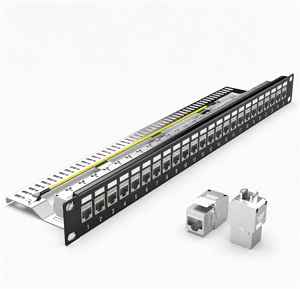
Splice boxes keep joints of fiber-optic cables safe from external stress and manage excess cable lengths. They are also referred to as Optical Termination Boxes. The GZR Series 19" Rack-mounted Terminal Box (Rail-based) is a functional component for optical fibre distribution frames or network integrated cabinets, offering fibre splicing, distribution, and tray storage. CAHORS offers complete solutions for FTTH distribution in residential. OTRANS provides professional, high-quality rack mount fiber patch panels (also known as fiber termination boxes) designed for modern data centers and network infrastructure. Our comprehensive range, from 1U to 4U standard 19-inch panels, offers scalable port densities (12 to 96 ports) to meet your. Distribution Cabinet Box – The Multi-Operator cabinet is a grouping module for fusion, coupling and connection of up to 48 fibers. Our boxes serve as a connection point for incoming and outgoing cables, providing cable termination, organization, and protection. GAO's box includes features such as cable. With the growing global deployment of Fiber-to-the-Home (FTTH) networks driven by the demand for ensuring high-capacity broadband services, mobile network operators (MNOs) face challenges of excessive energy consumption (EC) of wired optical access networks (OANs). This paper presents a.
[PDF]

ITU & IEC allow 0. 75 dB loss per mated pair. Splitter loss values are "Typical" and include a connector in and out. These values are approximate and should not be exceeded by more than 1-1. 5 dB, which could indicate dirty connectors, bad splices, or. ITU & IEC allow 0. These are known as passive optical splitters, and they perform the function. Let's start with the simplest part: the ideal, theoretical loss caused purely by dividing the light equally among N paths. This is often called Distribution Loss or Ideal Split Loss. Understanding the types of splitters, their impact on network performance, and how to measure their losses ensures high-quality network operation and facilitates optimal splitter selection based on. Use 2×N when two inputs feed the same distribution stage. Common values: 2, 4, 8, 16, 32, 64. Wavelength is recorded in outputs for documentation. 5 dB depending on splitter type. Fusion splices often plan around 0. Optional: patch. Excess loss is the ratio of the optical power launched at the input port of the splitter to the total optical power measured from all output ports. It assures that the total output is never as high as the input. Components, such as fiber cables, splitters, and switches, introduce attenuation. The maximum allowable distance between a transmitting laser and receiver is based upon.
[PDF]

Start by separating your Ethernet cable into two separate cables and connecting them to the back of the Ethernet cable splitter. Once the cables are securely connected, connect the other ends to your desired devices. Ensure that the cables are tightly secure and that all connections. When you need to connect multiple wired devices like computers, printers, and IP phones, but only have one Ethernet wall port, using an Ethernet splitter or network switch can expand your connectivity without rewiring. This guide explains your options and helps you choose the best solution for your. An Ethernet splitter is a small device that allows two Ethernet-connected devices to share a single cable run. It does not increase speed or create extra bandwidth. It simply divides signal pairs. This tool works best in basic setups where running another cable is not possible. An Ethernet splitter. Ethernet cable splitter wiring diagrams are essential for anyone who needs to connect multiple devices in a home or office network. With the ever-increasing popularity of high-speed internet and streaming services, providing reliable connections to multiple devices is becoming increasingly. An Ethernet splitter doesn't actually split a single Ethernet connection to provide separate internet access to two devices. Instead, it utilizes only two of the four pairs of wires within a single Ethernet cable to connect two devices, requiring two splitters for the setup to function correctly.
[PDF]

When working with laser light, a plate or cube beamsplitter offers the best combination of optical performance and power handling. a beamsplitter is choosing the right coating. Beamsplitters are optical components used to split incident light at a designated ratio into two separate beams. Additionally, beamsplitters can be used in reverse to combine two different beams into a single one. Beamsplitters are often classified according to their construction: cube or plate. A beamsplitter is an optic that splits light into 2 directions. The split ratio of light transmittance and reflectance is 1:1 and is called a half mirror. Good fit for large beam size applications at a reasonable price. This precise ability to direct light paths makes beam splitters essential in various applications, including imaging systems, laser. Plate beamsplitters are made using a coated substrate, and thus exhibit beam offset and ghost reflections from the second surface. Cube beamsplitters avoid beam displacement by working at 0° angle of incidence and placing the coated surface between two right angle prisms, but power handling can be. This Beamsplitters Selection Guide outlines the core types of beamsplitters, explains how they work, and provides practical advice for choosing the best one for your application. Newport offers a wide variety of Beamsplitters in various shapes.
[PDF]

They are designed to split unpolarized light at a specific Reflection/Transmission (R/T) ratio with unspecified polarization tendencies. A beam splitter or beamsplitter is an optical device that splits a beam of light into a transmitted and a reflected beam. It is a crucial part of many optical experimental and measurement systems, such as interferometers, also finding widespread application in fibre optic telecommunications. This division allows for the simultaneous analysis or utilization of the light's properties along two separate paths. The device is purely. Transmission and Reflection by. In addition to the task of dividing light, beamsplitters can be employed to recombine two separate light beams or. Explore the precision, applications, and design principles of beam splitters, essential for advancements in scientific research and technology. With WDS, a single X-ray energy – monochromatic X-rays – are counted at any given time. 19511; JEOL L-Value table2; CAMECA® SXFiveFE brochure3; Oxford Instruments Wave brochure4; Thermo ScientificTM NORANTM IbeX5). Unlike conventional beam splitters, PBSs ensure that the resulting beams are both linearly.
[PDF]
