
Splice Diagrams or Matrices capture an electric or optical network inside a location – documenting cables, ported equipment, and connections. Splices are fiber-to-fiber, port-to-fiber and port-to-port. Fiber optic cable splicing involves joining two fiber optic cables together. Another method of connecting optical fibers is termination or connectorization, which consists of processing the end of a fiber optic bundle so that it can be connected to other fibers or devices through fiber optic. In this guide, we cover the basics of fiber optic splicing, how to perform splicing using two different methods, and finally some best practices to perform good fiber splicing. Ensure Your Splicing Tools are Clean – #2. Use and Maintain Your. What to show on a network diagram? Fiber optic network diagrams represent the architecture and connectivity of fiber optic systems, and their design philosophy integrates technical, functional, and conceptual aspects. The diagrams abstract complex details of fiber optic systems to make them. This Geoschematics drawing remains easy to read despite containing more than 2000 fibers and 500 splices. All students and instructors must wear safety glasses in this lab. It is copyrighted by the FOA and may not be distributed without FOA permission. This VHO covers similar material to the videos on YouTube. The lab manual has several.
[PDF]

It describes three main splicing methods - de-matable connectors, mechanical splices, and fusion splices. Mechanical splices have higher losses than fusion splices. Fusion splicing welds two fibers together using an electric arc and provides the lowest loss. Executive Summary: A fiber optic pigtail is one of the most commonly specified yet least understood components in structured cabling. Get the wrong connector type, the wrong polish, or skip proper fusion splicing technique—and you're looking at elevated signal loss, increased back reflection, and a. Fiber optic cables are the invisible highways of our digital world, carrying massive amounts of data at the speed of light. But what happens when you need to join two cables to extend a network or repair a break? You can't just twist them together. This is where fiber optic cable splicing—the. Fiber Optic Cable is a form of modern network cable that has a far greater capacity than electrical communication connections. Splicing is typically required during cable installation, maintenance, or network expansion. This is essential for extending network reach, repairing breaks, or connecting cables in data centers and telecom infrastructure. The goal is to align the microscopic glass cores (typically.
[PDF]

The Optical Time Domain Reflectometer (OTDR) is useful for testing the integrity of fiber optic cables. It can verify splice loss, measure length and find faults. The OTDR is also commonly used to create a "picture" of fiber optic cable when it is newly installed. The Contractor tasked to perform testing or splicing on any fiber optic cable will follow these testing standards to fulfill their contractual obligations. The Contractor must utilize the correct equipment and testing techniques to gain acceptance, or the work cannot be approved. Later, comparisons can be made. For every fiber optic cable plant, you will need to test for continuity, end-to-end loss and then troubleshoot the problems. If it's a long outside plant cable with intermediate splices, you will probably want to verify the individual splices with an OTDR also, since that's the only way to make. ic system. Fiber optic testing of a newly installed system not only verifies that the system meets its design requirements, but also creates a performance baseline for all future testing and troubleshooting of t at system. What is Fiber Optic Splicing and Why is it Needed? – #1. Use and Maintain Your. This guide reveals the secrets to fusion splicing with little fluff—just proven, straightforward techniques refined from years of work in the field. The guide provides the complete workflow, covering safety precautions, tool selection, fiber preparation, fusion operation, quality control, and.
[PDF]

In this guide, you will find a chronological description of the fusion splicing process, the principal technical standards, and answers to the real-life questions network engineers and procurement teams may have. TMM P021 OPTIC FIBRE CABLE JOINING, TERMINATION & MANAGEMENT Version 9. Therefore, we will also touch on cost factors, risk management, and best practices in. Fusion Splicing • Splicing is the process of connecting two bare fibres directly without any connectors. • Splicing provide much lower insertion loss compared to fiber connectors that's why Splicing is preferred over the use of Connectors. Fiber mechanical splicing – Insertion loss < 0. 5dB Fiber. What is Fiber Optic Splicing and Why is it Needed? – #1. Ensure Your Splicing Tools are Clean – #2. 56 was approved by ITU-T Study Group 6 (2001-2004) under the ITU-T Recommendation A. 8 procedure on 14 May 2003. The International Telecommunication Union (ITU) is the United Nations specialized agency in the field of telecommunications. By following the step-by-step guide provided, you can effectively perform fusion splicing to maintain high-quality fiber optic.
[PDF]

Fiber loopback offers numerous advantages in testing optical networks. One of its primary benefits is its ability to provide an end-to-end testing scenario, simulating real traffic conditions and allowing comprehensive assessments of network performance. Additionally, fiber loopback devices are. Given that the signal does not leave the device, a failure revealed during fiber loopback testing is always an indicator of an error with the transceiver and/or internal configuration and not with the fiber-optic connection. Fiber loopback finds extensive applications in various phases of network. Therefore, the fiber optic loopback streamlines the troubleshooting workflow, significantly reduces network downtime, and ultimately lowers operational costs. The market offers a diverse range of Fiber Optic Loopback devices, each designed to meet specific testing requirements related to different. Fiber loopback cables are essential for networking testing, and troubleshooting to validate the performance and integrity of optical links. Whether used in pre-deployment testing or ongoing diagnostics, fiber loopback cables are important tools for maintaining optimal network operations and. 4. 3 Advantages of Loopback Testing No live network required: Ideal for lab and deployment verification. Fast diagnosis: Can instantly confirm whether a device port is operational. We hope you find this guide helpful. What are loopback cables? What are loopback cables? A loopback.
[PDF]

Provides technical requirements concerning the construction, testing, and performance of metal cable tray systems. It is the first joint effort of NEMA and CSA International to put in one place standards for metal trays per both NEMA and CSA methods. Addresses shipping. Cable trays play a vital role in supporting electrical cables and wires in commercial, industrial, and utility installations. For proper installation, design, and maintenance, adherence to international standards is essential. One of the most recognized frameworks globally is the IEC standard for. association representing the major electrical equipment manufac-turers in the U. The Cable Tray ng standards, performance standards, test standards and application in this document have been tested extens ompetent professional en completely installed, without damage either to conductors or. CABLE TRAYS THE GLOBAL SPECIALISTIN ELECTRICAL AND DIGITAL BUILDING INFRASTRUCTURES TECHNICAL GUIDE Not all cable trays are equivalent. The mechanical and electrical characteristics, tests, certifications, overall quality management, recommendations mentioned in this technical guide only apply to. Not all cable trays are equivalent. For those of you that have experience working with cable tray systems, you have probably noticed the high-level of influence NEMA has in guiding cable tray management projects.
[PDF]
Fiber testing is the process of verifying the performance of optical fiber cabling. This process includes a range of tests and measurements such as insertion loss, optical return loss, and fiber length. It encompass.
[PDF]
The operation and skills of fiber optic fusion splicing technology can be mainly divided into five steps: fiber stripping, fiber cutting, fiber melting, fiber sleeve, and fiber winding. In this guide, we cover the basics of fiber optic splicing, how to perform splicing using two different methods, and finally some best practices to perform good fiber splicing. What is Fiber Optic Splicing and Why is it Needed? – #1. And tools used for fiber fusion: fusion splicer; fiber cleaver; cable stripper; fiber optic stripper; alcohol;. Splicing fiber optic cable is an extremely important phase for making dependable, high-speed communication infrastructures. Regardless of the type of fiber network you're deploying, be it for telecom, enterprise data centers, or smart city infrastructure, fusion splicing provides the benefits of. While a cut or damaged fiber optic cable can temporarily take your network down, it is possible to quickly fix the cable with the right tools. In this video, we walk through the essential steps of preparing and splicing a fiber optic cable. Watch the complete process, from carefully stripping the fiber coating and performing a precision cleave, to loading the prepared fiber into the fusion splicer for a perfect alignment. Before jumping into the physical steps, it's important to understand the two primary methods of fiber splicing: fusion splicing and.
[PDF]

Multimode Fiber Optic Cable Material Selection & Receiving Inspection Checklist Verify that the received materials have been inspected for damage and for compliance to applicable requirements Cable Reel. Multimode Fiber Optic Cable Material Selection & Receiving Inspection Checklist Verify that the received materials have been inspected for damage and for compliance to applicable requirements Cable Reel. In the intricate realm of Fiber Optic Cable Manufacturing, precision and efficiency are paramount. Embracing the use of meticulously crafted forms and checklists offers a transformative advantage. These tools serve as indispensable guides, ensuring systematic adherence to crucial manufacturing. This article is about Multimode Fiber Optic Cable Material Selection & Receiving Inspection Checklist of Outside Plant (OSP) Telecom Distribution System as per International Codes and standards. Cable Reel Storage and Protection is as per Manufacturer's Recommendation. Verify all equipment and. Stranding order, pitch and colors. Core integrity Note: The above QAP is tentative only, vendor may provide their QAP after placement of order and before material delivery. NEIS® are intended to be referenced in contrac documents for electrical construction ation or liability to users of this publication. Existence of a standard shall not preclude any member or nonmember of NECA or FOA from specifying or using.
[PDF]

Examine for any signs of overheating or arcing. Verify that the box is securely mounted and that there are no loose connections. Internal Inspection Open the distribution box and check for dust and debris accumulation. In this inspection article, we will learn about inspecting the main electrical panelboard, from the utility service to the breakers, including common components of the panelboard, and an inspection checklist. Let's begin with InterNACHI's Home Inspection Standards of Practice. Home Inspection. This article series discusses procedures for safe and effective visual inspection of residential electrical systems including electrical panels and other components, when the inspection is conducted by trained building inspection professionals, home inspectors, electrical inspectors, and. In low-voltage electrical systems, LV non-intrusive switchboards control and distribute power. It protects, controls, and monitors building electrical circuits. Non-intrusive means the switchboard can monitor and operate the electrical system without directly interference with the electrical wiring. Use our electrical panel inspection checklist to identify potential issues, ensure routine maintenance, and prevent costly failures of electrical systems. Ensure that all labels and warning signs are legible. This 8-point list covers key areas of your electrical system, helping prevent costly repairs and protecting your property. From electrical panel safety and wiring.
[PDF]

Learn how to install fiber splice trays inside an enclosure step by step. Quick, easy, and essential for fiber pigtail management! https://bit. Unlike fiber connectors, which can be plugged and unplugged, splicing creates a fixed connection that is typically more stable and has lower insertion. This document describes the installation of optical fiber with both single fiber and/or ribbon fiber splices into Optical Splice Enclosure (OSE) metal splice trays (Figure 1). Make sure you read and understand this instruction as well as instructions provided with related assemblies before. By following these detailed steps, the installation of your Fiber Splice Closure will be secure, organized, and maintained, ensuring high performance and longevity of your fiber optic network. Installing a fiber optic splice closure efficiently and effectively requires attention to detail and. How to install the splitter distribution box is the important information we need to know. This article includes the following: 1. Install the fixture 2. Box installation and fixed splitter distribution box 4. Install. Page 5 B (# 7 & 8) enter splice tray # 2. Route the fibers entering the splice tray up to splice point as shown. NOTE : Protection tube from side A enters splice tray from the far end as shown After splicing, close the splice tray and lock the front cover properly with the main and side lock.
[PDF]
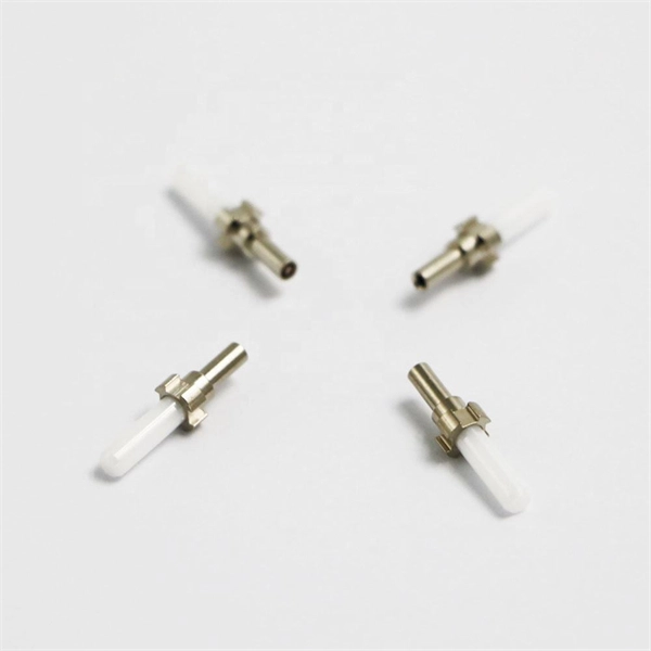
When the heat-shrinkable tube is tightened after splicing, the residual pollutants (such as tiny sand particles) will press the optical fiber and cause the optical fiber to deform, so the splicing loss will increase. At this time, the fiber needs to be cleaned. A fiber optic pigtail is a fiber optic cable with one end terminated with a factory-installed connector and the other end unterminated. As a result, the connector side can be connected to equipment, while the other side is fused in the case of fusion splicing and a mechanical connection in the case. Executive Summary: A fiber optic pigtail is one of the most commonly specified yet least understood components in structured cabling. The guide provides the complete workflow, covering safety precautions, tool selection, fiber preparation, fusion operation, quality control, and. Removes the protective coating to expose the bare fiber for splicing, ensuring no scratches or nicks. Produces a clean, precise fiber end face, critical for low-loss fusion or mechanical splicing. Precisely aligns and fuses fiber ends to form a stable, low-loss connection suitable for long-term. The scientific fiber coiling method can make the optical fiber layout reasonable, the additional loss is small, can withstand the test of time and harsh environment, and can avoid the phenomenon of fiber breakage caused by extrusion. Optic Fiber Management Rules 1. Coil the fibers along the.
[PDF]
This comprehensive checklist helps facility managers and maintenance personnel identify potential issues with fire-rated cable tray covers before they lead to compromised fire safety, electrical hazards, or building code violations. Regular inspection of fireproof cable tray covers is essential for maintaining electrical system safety and fire protection integrity. Why Are Cable Tray Inspections Important? Cable trays serve as the backbone of electrical systems, ensuring. The fire-resistant cable tray and conduit assemblies play a critical role in maintaining safe and compliant industrial operations, particularly within hazardous locations such as chemical plants, oil refineries, and manufacturing facilities. One of the most widely recognized testing standards for. Scope: Firestopping for busway, cable trays, cables, and trunking passing through walls in enclosed electrical installations. Where cables pass through shafts, walls, slabs, or enter electrical panels or cabinets, openings shall be tightly sealed with firestopping materials in accordance with. Fire safety is paramount in any electrical system, and cable trays play a crucial role in ensuring the protection and reliability of the infrastructure. At Hutaib Electrical, we understand the importance of implementing robust fire safety measures to safeguard both people and property.
[PDF]
