A single-mode fiber optic cable is an optical fiber designed to propagate light signals over long distances with minimal attenuation. It comprises one glass or plastic fiber and features a tiny core of about 8-10 microns in diameter. There are two main types of fiber optic cables: single mode and multimode. Although they can do the same job in some instances, the different construction methods make each of them better suited to certain tasks and budgets. That makes picking between single mode and multimode fiber optic cables an. Single mode fiber optic cable is made up of a small diameter glass or plastic core surrounded by cladding, which is a layer of reflective material. This small core permits only one light mode to propagate through. From the fiber core and core size to single mode fiber and multimode fiber cables, each type of optical cable serves a specific purpose depending on transmission distance, network requirements, and installation environment. In this guide, Omnitron Systems explores the key differences between. Unlike copper cables, which rely on electrical signals, fiber optics use pulses of light to transmit data—offering unmatched bandwidth, low interference, and long-distance capabilities. OS2 cable offers low signal attenuation and high bandwidth. For more detailed information, you can refer to the article Single Mode Fiber Wiki: Types and.
[PDF]

In this guide, you will find a chronological description of the fusion splicing process, the principal technical standards, and answers to the real-life questions network engineers and procurement teams may have. 📦 For purchasing, use the RP Photonics Buyer's Guide for fusion splicers. It provides an expert-curated supplier directory, buyer-focused technical background information, and structured selection criteria to support professional procurement decisions. This article explains the principle of fusion. Fusion splicers play a crucial role in the field of optical fibre communications by enabling the permanent bonding of two strands of glass fibre to create a continuous pathway for light to travel through. This process is achieved through precise alignment and fusion of the fibre ends using an. Fusion splicing is the process of fusing or welding two fibers together usually by an electric arc. Fusion splicing is the most widely used method of splicing as it provides for the lowest loss and least reflectance, as well as providing the strongest and most reliable joint between two fibers. Each splicer is equipped with a cleaver and stripper, conveniently includes in a single case. The goal is to align the microscopic glass cores (typically.
[PDF]

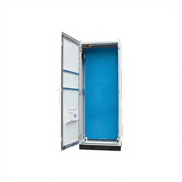
A blinking red light on a ZTE WiFi 6 router typically indicates that the router is powered on but isn't receiving an internet signal from the fiber line, or the connection hasn't been fully activated by the provider. First, check the physical connection between the. This guide will walk you through what the LOS light means, why it blinks red and step-by-step instructions on how to resolve the issue, including resetting your router. NSI-79750LW Round Indicator Light with Non Replacable Lamps, Press Fit, 0. 5" Panel Cutout, 0. uxcell 2Pcs Red Green Indicator Light. That blinking red LOS light means your router has lost its connection to your internet provider's network. Before you panic or call tech support, there are several simple fixes you can try at home that often solve this problem in minutes. The LOS light on your router stands for “Loss of Signal. Understanding the possible causes and fixes for this issue is crucial to getting your connection back on track. We will explore common reasons behind the solid red.
[PDF]

Installing FTTH wall outlets the right way improves internet speed. It also lowers signal loss. Pick the correct outlet type for your space size. Use single-port for small areas and multi-port for bigger networks. Use good tools and materials to protect the delicate fiber optic cables. Designed to provide a clean, secure, and accessible termination point for indoor fiber connections, these outlets ensure optimal signal quality and minimal interference in residential and commercial environments. Whether you're a homeowner upgrading to fiber or a contractor planning network. These outlets act as the key connection point between your fiber optic cables and the devices that require fast, stable internet access. What is a Fiber Wall Outlet Socket? A fiber wall outlet socket is a specialized socket installed in walls or other surfaces to terminate fiber optic cables in a. When you're looking to bring the unparalleled speed and reliability of fiber optic cable into your home, the preparation phase is crucial. This small device helps send data quickly and smoothly. It supports fast internet and steady communication. A good setup cuts signal loss, lowers. Indoor cables can be installed in raceways, cable trays above ceilings or under floors, placed in hangers, pulled into conduit or innerduct or blown though special ducts with compressed gas. The installation process will depend on the nature of the installation and the type of cable being used.
[PDF]

Learn how to splice fiber optic cable using fusion splicing with this complete step-by-step guide. Includes tools, best practices, loss standards (ITU-T G. 652), cost analysis, and FAQs for network engineers and installers. Fiber optic cables can be connected together using a couple of different methods: 1. Fusion Splicing: This method involves aligning the ends of the two fiber optic cables and then fusing them together using heat. This creates a permanent and low-loss connection. This article will guide you through the necessary tools, materials, and methods on how to connect fiber optic cables effectively. Fiber optic adapters, also known as couplers, play a crucial role in fiber optic networks by providing a connection point between two fiber optic connectors. They enable seamless and reliable optical signal transmission between different fiber optic cables, connectors, or devices. Regardless of the type of fiber network you're deploying, be it for telecom, enterprise data centers, or smart city infrastructure, fusion splicing provides the benefits of. Mastering the art of connecting two optical fibers is essential for ensuring optimal network performance and stability. The connector is made and well test. Simply plug and play. However, the length is fixed with a pre-made fiber optical cable. You can't get all the length you need. In this video, you will see how to use the LC coupler to join two.
[PDF]
Thus, a fiber termination box is used to terminate the optical fiber cables in the field and connect them to the pigtail by splicing. After an optical cable arrives at the user's end, it is fixed in the terminal box.
[PDF]
Fiber optic cables are often perceived as being fragile and prone to breakage, but this is not entirely accurate. While it is true that fiber optic cables can be damaged if they are bent or flexed too much, they are actually quite durable and can withstand a significant amount of. Fiber-optic cables are the backbone of modern connectivity—powering 5G networks, global internet backbones, and data center interconnections with near-light-speed data transmission. Tension and stress: Fiber optic cables can be damaged if they are subjected to too much tension or stress, as this can cause the fibers to break. To ensure they can fulfil these requirements, developers created and refined fiber optic cables. These cables are made of small strands of fine glass inside an insulating sheath. These tiny glass strands are different from the typical wires you might see in other kinds of cabling. Here are some key points to consider: Installation Processes: During the installation of fiber optic cables, improper handling or excessive tension can lead to damage. Connectors and interfaces, which are relatively. While the glass fibers inside are fragile, modern fiber cables are engineered to withstand crushing forces, extreme temperatures, and even rodent attacks—making them vital for harsh environments. Contrary to myth: A single optical fiber can support 8 kg (17. The cost of a single optical switch can range from $500 to $5,000 or more, depending on the.
[PDF]
Thus, a fiber termination box is used to terminate the optical fiber cables in the field and connect them to the pigtail by splicing. After an optical cable arrives at the user's end, it is fixed in the terminal box. A fiber pigtail is a specific hardware connection used for cable termination. Fiber adapters: These are used to connect the fiber optic cables to the fiber termination box and should comply with industry. This article will guide you through the necessary tools, materials, and methods on how to connect fiber optic cables effectively, ensuring you achieve optimal performance from your fiber optic network. Have a network installation project? Fiber Optic Cables: The primary medium for your connections. To establish easy and safe installation put the box where it will be installed and measure the required length of the cable. Prepare the safe installation of the box. 5 meter or more, to. Learn how to install a fiber optic termination box step-by-step for FTTH projects. Covers mounting, splicing, routing, labeling, and testing for indoor/outdoor use. Installing a fiber optic termination box is one of those jobs that looks simple on paper, but it's easy to do poorly in the field. Preparations: Before installation, please ensure that you have obtained optical fiber network access services.
[PDF]
Single mode and multimode fiber optic cables are two different types of fiber optic cable aimed at different use cases. Single mode cables are typically made with a single strand of glass at their core, leading to a n.
[PDF]

Fiber optic network diagrams represent the architecture and connectivity of fiber optic systems, and their design philosophy integrates technical, functional, and conceptual aspects. The diagrams abstract complex details of fiber optic systems to make them understandable for. Fiber optic network design refers to the specialized processes leading to a successful installation and operation of a fiber optic network. It includes first determining the type of communication system (s) which will be carried over the network, the geographic layout (premises, campus, outside. A fiber optics network diagram illustrates how high-speed data travels from an internet service provider to end users. These diagrams help engineers plan infrastructure for residential and commercial buildings. It includes detailed mapping of backbone, distribution, and drop connections for FTTH, FTTP, FTTx, and enterprise networks. Planning and design is a process that includes many decisions, involving first defining the communication protocols to be used on the network and defining geographical layout. It also involves selecting transmission equipment.
[PDF]

Mode conditioning cables serve as effective solutions for enabling gigabit Ethernet transmission over existing multimode fiber optic networks. Operating at 1300nm, they are specifically engineered to mitigate modal dispersion. This page lists all of our OM1 and OM2 fiber optic mode conditioning patch cable products. If you try to connect multi mode to single mode fiber patch cables without mode conditioning. FS offers OM1 & OM2 mode conditioning fiber optic patch cables (MCP) in any connector & cable length, optimal for eliminating differential mode delay effects. We offer Mode Conditioning cables in all varieties and combinations of SC, ST, MT-RJ and LC in. The LightWave Mode Conditionig LC-LC Multimode OM1/Singlemode OS2 Fiber Optic Patch Cable is a Optical Mode Conditioning cable that incorporates Multimode 62. 5/125 and Singlemode 9/125 glass to allow a Singlemode Transiever to communicate to a Multimode Tranceiver. These cables are constructed with a centerline offset splice. Mode Conditioning Patch cords are used to connect multimode fiber plants that use transceiver modules. They are needed because transceiver modules use a single mode launch condition even when they are being used with multimode fiber. These cables are easily installed without any additional fiber.
[PDF]
Picking up the best router for fiber internet isn't just about going to the market and choosing one of the best wireless routers. Instead, you need to carefully look at its specs, performance, and the type of securit.
[PDF]

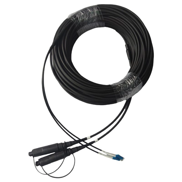
ADSS fiber cables demand site surveys, route planning, and correct mounting hardware. The best practice includes tension checks, buffer tube management, and regular lash-back tests to keep the cable stable. Maintenance includes routine inspections, cleaning, and load checks. These steps help prevent breaks and signal loss. Many engineers trust these methods to ensure stable performance over long spans. All Dielectric Self Supporting (ADSS) Fiber Optic Cable Installation The practices contained herein are designed as a guide. Since there are numerous practices which may be utilized, Prysmian has tested and determined that the practices described herein are effective and efficient. The recommended. Q1: What fiber core counts are available for this ADSS cable? A1: Usually offered in 4, 6, 12, 24, 48 cores, and custom cores can be added as needed. Q2: What fiber type: single-mode or multi-mode? Standards compliance? A2: Generally single-mode fiber complying with ITU-T G. 657. This procedure provides general information for installing all Corning Optical Communications Solo® ADSS All-Dielectric Self-Supporting fiber optic cables from 2-288 fibers. Each installation will be influenced by local conditions. As someone who has worked on numerous ADSS projects at Bright Power Co., Ltd, I've faced challenges ranging from cable sag to high-voltage.
[PDF]


