Time domain reflectometers are commonly used for in-place testing of very long cable runs, where it is impractical to dig up or remove what may be a kilometers-long cable. They are indispensable for preventive maintenance of telecommunication lines, as TDRs can detect resistance on joints and connectors as they corrode, and increasing insulation leakage as it degrades and absorbs. OverviewA time-domain reflectometer (TDR) is an electronic instrument used to determine the characteristics of by observing. It can be used to characterize and locate faults in metallic cables (for. A TDR measures reflections along a conductor. In order to measure those reflections, the TDR will transmit an incident signal onto the conductor and listen for its. If the conductor is of a uniform.
[PDF]

OTDR is essential for diagnosing and ensuring the integrity of single-mode fiber optic cables. Understanding OTDR traces involves analyzing backscatter, reflection events, and attenuation. Proper interpretation of OTDR reports aids in effective troubleshooting and maintenance of fiber. Download free OTDR Trainer Software for PCs After you study this page, you can download a free OTDR Trainer to run on your PC. It can verify splice loss, measure length and find faults. The OTDR. The Optical Time-Domain Reflectometer (OTDR) is a fiber fault diagnostic tool recommended by standards such as the International Telecommunication Union and the International Electrotechnical Commission. However, the level of complexity involved requires a great amount of knowledge and expert skills to use it efficiently. The OTDR trace tells a story about each fiber it tests. A certain dip or spike known as an event can reveal the type of connection. Lets take the example below: This link has pretty much every type of event you nay expect to see. Lets break them down one by one: This is a reflective event and. Fiber optic networks require precise testing to maintain performance, and an Optical Time Domain Reflectometer (OTDR) is a key tool for this. OTDR trace results provide insights into fiber health, identifying faults, splice losses, and reflections. However, interpreting these traces can be.
[PDF]
In normal operating conditions the power consumption of a load is sometimes less than that indicated as its nominal power rating, a fairly common occurrence that justifies the application of an utilization facto.
[PDF]

This AutoCAD DWG file includes a complete Single Line Diagram (SLD) of a Distribution Board, showing circuit breakers, wiring connections, and load distribution for lighting, power, and mechanical systems. An electrical panel box, also known as a breaker box or a distribution board, is a crucial component of any electrical system. It serves as a central hub for distributing electricity throughout a building, ensuring that power is delivered safely and efficiently to all the required locations. Whether you're an electrician or a DIY enthusiast, this guide will help you understand the basics of home electrical distribution. What is Distribution Board? Distribution board. Welcome to our channel @Electricalgenius In this video, we'll take you through a detailed step-by-step guide on wiring a home distribution DB (Distribution Board) box. A distribution board (also known as a service panel or breaker box) is a centralized collection of circuit breakers, fuses, and/or relays used to control and protect the wiring in a home. The diagram. To understand how a breaker box works, it is helpful to have a wiring diagram that shows the connections between the various components. At the heart of a breaker box is the main breaker, which controls the flow of electricity from the utility into the building. This breaker is connected to a.
[PDF]
The usage agreement governs how much transmission capacity the customer subscribes to. The customer pays a fee for his subscription according to the grid tariff's capacity fee. The capacity fee shall cover t.
[PDF]
You are looking at $0. The price swing usually depends on the fiber count (e., 12-core vs 96-core) and brand. Generic glass is cheap; premium glass (like Corning) costs more but guarantees lower attenuation. You are looking at $0. It is composed of 6 multimode fibers (50 micron core) inside a water blocking Aramid yarn wrapped in a black PVC outer jacket. Commercial building installations with 100-200 network drops generally range from $15,000 to $30,000. Single-mode fiber costs less per foot than multimode fiber, but it requires more. The unit cost of fiber optic cables can vary from $0. Here's a general pricing reference: Cable TypePrice Range (USD/meter)Simplex / Duplex Indoor Cable$0. 30Single-mode Outdoor Cable$0. 50Multimode (OM1/OM2/OM3)$0. 10 –. The price of fiber optic cabling depends on cable type, length, installation method, and surrounding materials. Typical costs hinge on fiber count, indoor versus outdoor use, and whether trenching, splicing, or termination is required.
[PDF]

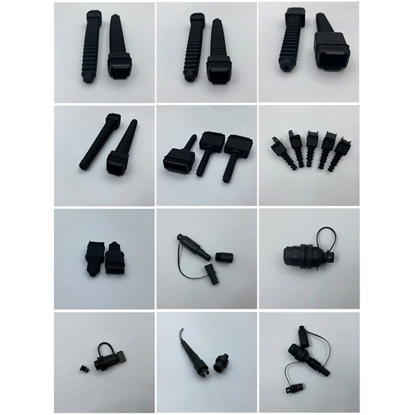
Traditional Fusion Splice-On Connectors with pigtails provide factory-polished performance with field-termination convenience within harsh environments. Mass fusion splicing can fuse up to all 12 fibers in one ribbon at once. Standard ® offers an ever-expanding line of connectors in more than 300 categories. All of our connectors are manufactured with high-quality materials and tested to match OE fit, form and function and perform in harsh conditions. 93 Original price was: $1. Add to cart Sale! Add to cart Sale! Add to cart $ 0. Add to cart. 3M™ Mini D Ribbon (MDR) Connectors, 102 Series are. 050″ boardmount thru-hole right angle receptacle-shielded. It is is the industry standard for half-pitch I / O connectors widely used in various electronic devices such as internal and external computers, OA, FA, ME as a system for connecting. ependable, and trouble free splicing on site. These Pigtails shall be used to ensure effici nt use of space and rapid network deployment. Ribbonized Fiber is optimal for mass-fus r by phone: 800. Beginning with the right side of the bottom tray, insert pigtailed EDGE modules into the housing, if they are not already installed. route ribbon pigtails from the modules and the ribbons from the cable to the opposite side from where the cable(s) enter the housing. Loosely capture the ribbons with.
[PDF]

Have all of our in-stock product information and specifications right at your fingertips in digital PDF format. is a world class manufacturer of electronic wire and cable, both copper and fiber optic cable. Because of NATIONAL's service attributes and extensive cable manufacturing abilities, we offer a unique set of brand attributes: personalized service and product selection. You can get just about any. DOWNLOAD the Complete Catalog (PDF format 3. 9 MB) Download part numbers, descriptions and specifications of National Wire in-stock products by specific category or download the entire catalog. Heavy-Duty Flexible PVC Insulation – Crack-resistant and built for long-term durability. Versatile Use – Perfect for automotive, solar wiring, LED lighting, home projects, and RV systems. Guaranteed for. Fill out the form with your project details, and we'll help you every step of the way. Feedback! Don't miss out on anything, subscribe to our Newsletter! NNC © Copyright 2009 - 2026. Forgot your password?. Important! LANshack offers premium fiber optic cable & copper wire assemblies. We have all the components to optimize & install your network!. welcome to taobao purchase national standard soft copper wire 25 square millimeters 16 square millimeters copper core cable high-volume building welding machine welding wire welding machine welding machine welding soft copper wire.
[PDF]

Recommendation ITU-T L. 101 describes characteristics, construction and test methods of optical fibre cables for buried application. 0, in February 2016. The short answer, based on general industry standards and the National Electrical Code (NEC), is that fiber optic cable is typically buried between 24 inches (60 cm) and 30 inches (76 cm) deep. However, simply hitting this depth isn't enough to guarantee your network survives. Factors like the. Underground fiber optic cable installation follows specific standards that govern burial depth, testing methods, installation techniques, and safety requirements. 5 is an article in the National Electrical Code that addresses requirements for underground electrical installations, including minimum cover requirements—the measurement used to determine the distance from the top of an underground cable or raceway to the finished grade. 5. Estimate minimum burial depth (cover) for underground electrical, fiber, and low-voltage cable runs using a practical, code-aware ruleset. Use this page to plan trench depth, compare conduit options, and prepare for inspection conversations. Use this calculator to estimate a minimum burial depth. Recommendation ITU-T L. This depth is generally considered the absolute shallowest for any telecommunications cable that is not placed.
[PDF]

The FC/PC (Physical Contact) and FC/APC (Angled Physical Contact) fiber optic connectors are standardized under TIA EIA/TIA-604-4 and IEC 61754-13. ABSTRACT: This standard describes the point-to-point physical interface portions of Fibre Channel serial electrical and optical link variants that support the higher level Fibre Channel protocols includ-ing FC-FS, HIPPI, IPI, SCSI and others. This standard is recommended for new implementations but. Fiber connector types LC, SC, FC, ST, MTP, and MPO are widely used in past and present. What are the differences between them? Who is the most popular one? Find the answer in the article. What is a Fiber Connector? The optical fiber connector is a kind of detachable passive optical component used. An optical fiber connector is a device used to link optical fibers, facilitating the efficient transmission of light signals. An optical fiber connector enables quicker connection and disconnection than splicing. Unlike fiber splicing, which is permanent, connectors allow for easy connection and disconnection of cables, making them ideal for maintenance and flexibility in. Understanding fiber connector types—SC/APC, SC/PC, LC/UPC, LC/APC, ST/PC, FC/PC, and FC/APC—is essential for selecting the right interface for your application. Each type varies by shape, polish (APC, PC, or UPC), and return loss performance, which affect PC, UPC, and APC Polish Styles: What's the.
[PDF]

Bury cables from 12-36 inches (or 30-90 cm) deep. Where plant life, sidewalks, and other utilities already disrupt earth, it's safer to bury at as little as 24 inches or 60 cm, using protective conduits to limit the likelihood of damaged cables by inexperienced maintenance or. Bury cables from 12-36 inches (or 30-90 cm) deep. However, simply hitting this depth isn't enough to guarantee your network survives. Factors like the. Requirements vary based on location, cable type, and local regulations, with depths typically ranging from 18 to 48 inches. Residential areas require depths between 24 and 36 inches for most installations. This protects cables from landscaping activities and minor excavation work. This. The question of how deep to bury fiber optic cable has no single answer, as the required depth changes significantly based on location, environment, and specific application. Industry standards and regulations, such as those often referenced in the National Electrical Code (NEC), establish a. Fiber optic cables are typically buried between 12 and 36 inches (30–90 cm), depending on installation environment, soil conditions, and load requirements. In high-load areas such as roads or backbone routes, burial depth can reach 48 inches (120 cm) or more. This guide provides a comprehensive overview of industry.
[PDF]

A 1U server rack measures exactly 1. 45 mm) in height and fits standard 19-inch racks. For example, a typical full-size rack cage is 42U high, while equipment is typically 1U, 2U, 3U, or 4U high. The rack unit size is based on a standard rack specification as defined in EIA -310. The Eurocard specifies a standard rack unit as the unit of height; it also defines a similar unit. U (rack unit, RU) is a unit of equipment height in a 19" rack. Important: U describes height only, but a server's real "capabilities" are also determined by chassis depth, internal layout, airflow, rails, power, and expansion (PCIe/risers, NVMe. Originally defined by the EIA-310 standard, the rack specifies a front panel width of 19 inches (482. 6 mm), allowing different hardware from various manufacturers to fit in the same enclosure. The unit calculator below can convert rack U's into cm, inches and feet. You'll get the precise, standardized dimensions of a 1U server rack unit — including height (1. 45 mm), width (19″ / 48. This three hole grouping is known as a rack unit (RU) or “U”.
[PDF]