
The IEEE standard for protection relays refers to a collection of guidelines developed by the Institute of Electrical and Electronics Engineers. These standards define the performance, accuracy, reliability, and testing requirements of protective relays used in electrical systems. Relay systems protect high-voltage equipment and transmission lines to ensure safe, stable systems. Although failure of a protective relay system may have severe local or regional impacts, most protective relay systems are not required to operate to prove they are in working order. Many of the protective relay systems are seldom called upon to work and have little means of proving they. The testing and verification of relay protection devices can be divided into four groups: Type tests are needed to prove that a protection relay meets the claimed specification and follows all relevant standards. Since the basic function of a protection relay is to correctly function under abnormal. Protective relays are decision-making elements in the protection scheme for electrical power systems. A strong test and maintenance program will keep protective relays in a high state of readiness and help utilities avoid equipment damage and prolonged downtime. This guide provides recommended. This utility standard establishes the requirements for testing and maintaining protection systems, automatic reclosing, and sudden pressure relaying.
[PDF]

What is a Full Wave Rectification? Full wave rectifications are a specific type of rectification that transforms the entire AC signal cycle into a pulsing DC signal, one half at a time. Full-wave rectification converts alternating current to DC using numerous diodes. The full wave rectifier converts both halves of each waveform cycle into pulsating DC signal using four rectification diodes. In the previous power diodes tutorial we discussed ways of reducing the ripple or voltage variations on a direct DC voltage by connecting smoothing capacitors across the. Full Wave Rectifier Definition: A full wave rectifier is defined as a device that converts both halves of an AC waveform into a continuous DC signal. Circuit Diagram: The circuit diagrams for both centre-tapped and bridge rectifiers show how diodes are used to ensure the conversion of AC to DC. For the conversion of AC voltage into DC voltage it uses two different types of circuit configurations i. Center Tapped Full Wave Rectifier and Full Wave Bridge Rectifier. Output Voltage: Produces a pulsating DC output with twice the frequency of the. The process of converting the AC current into DC current is called rectification. Rectifiers are generally classified into two types: half wave.
[PDF]
Home appliances TV sets, VCR, Microwave ovens Office machines Industrial equipment NC machines, Robots, Temperature controllers Photocopiers, Vending machines. Space saving design Wiring can be done with ease (DIN terminal). N.C. contact raw N.O. contact raw COM contact raw Coil terminal raw. N.C. contact raw N.O. contact raw COM contact raw Coil terminal raw. For Cautions for Use, see Relay Technical Information.
[PDF]
Distance relays, also known as impedance relay, differ in principle from other forms of protection in that their performance is not governed by the magnitude of the current or voltage in the protected circuit but rather on the ratio of these two quantities.OverviewIn, a protective relay is a device designed to trip a when a is detected. The first protective relays were electromagnetic devices, relying on coils operating on moving par. Electromechanical protective relays operate by either, or. Unlike switching type electromechanical with fixed and usually ill-defined operating voltage thresholds. Electromechanical relays can be classified into several different types as follows: "Armature"-type relays have a pivoted lever supported on a hinge or knife-edge pivot, which carries a moving contact. These relays may.
[PDF]

Traditional electromechanical relays rely on fixed settings that cannot adapt to variable grid conditions. This often results in miscoordination, delayed fault clearing, or unnecessary tripping, compromising reliability. able sources such as wind and solar. These clean energy sources, connected through inverters and flexible transmission systems, are transforming traditional grids based on synchronous generators into more flexibl cant challenges to system stability. Nowhere is that clearer than in the challenge to. Relay protection systems are essential in maintaining the safety and reliability of modern electrical grids. As technology advances and grids become smarter, the tools used to test and maintain these systems, such as the relay test set, are evolving to meet new challenges. This article explores the. By taking a series of countermeasures, the paper explored the influence of new energy connection on traditional relay protection systems in response to the occurrence of the above phenomenon. These countermeasures include protection logic and settings optimization, fast fault detection technology. Abstract—This paper discusses the impact of inverter-based resources (IBRs) in traditional digital protection relays applied in the interconnection transmission line between the IBR and bulk power system. This paper explores the development of relay protection technology in smart grids, analyzing.
[PDF]
of relay protection coordination for a PV power plant connected to the distribution network is presented. In recent years, installation of PV power plants in the distribution network has increased significantly. I.
[PDF]

This video provides a detailed walkthrough of designing and simulating an automatic light control system using Light-Dependent Resistor (LDR) and Triac in Proteus Software. Last updated on 13 August 2025 by Admin-Lavi Leave a Comment This article talks about Light Controlled Switch Circuit using IC LM311 and LDR. It simple and very useful and it feel light change near it. We find this circuit in many place like automatic light, street lamp and security system. Main. ABB's Control Room offering includes a comprehensive range of solutions designed to optimize the operator workspace for critical 24/7 processes across various industries. The project demonstrates how to create a smart lighting system that turns on/off automatically based. more This video. The Intro Screen changes as you play with it. It has a Play Area and a Control Area. A Construction Area creates a building space for components added from a Circuit Component Toolbox. Build and navigate your circuits there. If Voltmeters and Ammeters are out of the toolbox, you can take. Common sense schematics let you name a node "+5V" and know that the simulator will do the right thing automatically, keeping your schematics compact and elegant. This circuit activates or deactivates connected loads, such as LEDs or light bulbs, based on ambient light levels.
[PDF]
The procedures of testing switchgear, instrument transformers and relays are explained in detail. The close and trip, indication and alarm circuits for variety of circuit breakers indicating ferrule numbers are al.
[PDF]

Free electrical load calculation tool for residential and commercial buildings. Calculate service entrance sizing, panel loads, demand factors, and ensure NEC Article 220 compliance. Always verify calculations with a. Electrical load calculation is a critical process in electrical design that determines the total electrical demand of a building or facility. Proper load calculations ensure that electrical systems are safely designed with adequate capacity for present and future needs. What is Electrical Load. What is Electrical Load Calculation? 1. Connected Load (CL) 2. Demand Factor (DF) 3. It accounts. This technical drawing presents a detailed residential electrical service cabinet and main power distribution layout with accurate load calculations. The image shows meter installation, service cabinet arrangement, MCCB panel board, isolator positioning, and incoming and outgoing cable connections. This standard only addresses fixed (or. Electrical load calculator estimates power demand, ampacity, and panel capacity, guiding circuit sizing, load balancing, voltage drop checks, and NEC-compliant design for residential, commercial, and industrial electrical projects, planning safely.
[PDF]

This video shows real on-site footage of electrical installation, demonstrating safe and standardized wiring methods used by professionals. A distribution box is the heart of any electrical system. It takes the incoming power and safely distributes it to different circuits throughout your building. Whether in a home or an industrial facility, this box keeps. Whether you are an electrical contractor or a construction brigade, knowing how to properly and safely install distribution boxes is the basis of ensuring the safe operation of the entire system. This article details the process of installing them, which helps you comprehend distribution boxes. In modern electrical systems, cable distribution boxes (also known as electrical distribution boxes or distribution boxes) play a crucial role as the key hub for managing, distributing, and protecting circuits. Whether it is residential buildings, commercial facilities or industrial sites, the. Identifying Symbols and Labels: The first step in reading an electrical panel box wiring diagram is to familiarize yourself with the symbols and labels used. These symbols represent different electrical components, such as switches, outlets, lights, and circuit breakers. Labels are used to identify. duct, please dispose the pro ormal operation due to poor manufacture quality. For any damage due to one of the following situations, a paid repair duct, please dispose the pro ype, a “R” is added after the Specification. For single row.
[PDF]

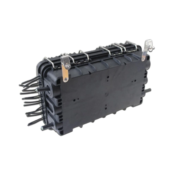
Search by product name or upload HTS codes to see real-time duty calculations. Tariff Simulator is provided for general informational purposes only to assist importers of record with their own corporate compliance activities. Get instant insights on how tariffs affect your imports. This tool does. The fiber optic termination box is great for jointing optical cable and pigtail or splitter, which can achieve cable direct and branch connection. The plastic splice box offers the functions of mechanical/fusion splicing, splitting, and distribution, It is waterproof and suits indoor and outdoor. The Optical Distribution Box is used as a termination point for the feeder cable to connect with drop cable in FTTx communication network system. The fiber splicing, splitting, distribution can be done in this box, and meanwhile it provides solid protection and management for the FTTx network. 【IP65 Waterproof】The optical fiber connector box is made of PC+ABS material, waterproof, anti-aging, dust-proof, can be used outdoors and indoors. Enjoy durable, efficient, and cost-effective solutions for your FTTH needs. Fiber-optic cable materials typically cost $1 to $6 per linear foot, depending on fiber count and cable type. Commercial building installations with 100-200 network drops generally range from $15,000 to $30,000. Single-mode fiber costs less per foot than multimode fiber, but it requires more.
[PDF]
From stunning modern cabinets to unique custom cabinets for kitchens, bathrooms and offices, we go the extra mile to give you the custom products you need. Begin your project today by calling us. We'd love to discuss our qualifications with you!. Lista provides today's most complete selection of workbenches, cabinets, workspace furniture, accessories, and more. We help you create work environments that: The result of high-quality construction, and innovative engineering and design, Lista products are built to provide functionality. Welcome to [Your Cabinet Business Name], your premier destination for high-quality cabinets in San Jose and the surrounding areas! Whether you're looking to revamp your kitchen, bathroom, or any other space in your home, we have the perfect cabinets to meet your needs. Our commitment to excellence. Custom Cabinets & Doors has been providing flexible service and superior craftsmanship to those in San Jose, CA and Santa Clara, CA since 1985. Neves Custom Cabinets, Inc. has been in business for over 15 years, and is owned and operated by Tony Neves and his sons Anthony and Nicholas. We are located in downtown San Jose, but do business throughout the entire Bay Area.
[PDF]

Shop high-quality Power Distribution Units (PDUs) at mmsrilanka. com — your trusted source for rack-mounted and surge-protected PDUs. Ideal for data centers, network racks, and IT environments. Explore aluminum body, UK socket, and smart power management s. Pdus - Basic Pdus. (For Power Distribution Of The Server Racks) Reliable power distribution panels for managing and distributing electrical power efficiently in IT and industrial setups. Designed for reliability and scalability, it ensures seamless power management, surge protection. We harness the power of Fusion 360, the latest in 3D engineering software, which prioritizes collaboration across multiple platforms, be it on a PC, mobile device, or tablet. With Fusion 360, we believe we can directly bring our vision to our clients Sometimes simulations are not enough, that is. Magline Switchboards Pvt Ltd is the leading manufacturer or low voltage power distribution panels. Sub distribution panels, Cable management systems and server rack systems for industrial and domestic applications in Sri Lanka. We have our own designing and manufacturing capability in house which. The Sri Lankan market offers distribution boards from budget basic units to high-specification, certified panels. The best choice hinges on balancing technical requirements, certification needs, budget, and order volume. Here are key recommendations based on the product data. Core Compliance.
[PDF]


