
Normal WDM (sometimes called BWDM) uses the two normal wavelengths 1310 and 1550 nm on one fiber. Coarse WDM provides up to 16 channels across multiple transmission windows of silica fibers. Dense WDM (DWDM) uses the C-Band (1530 nm-1565 nm) transmission window but with denser. In fiber-optic communications, wavelength-division multiplexing (WDM) is a technology which multiplexes a number of optical carrier signals onto a single optical fiber by using different wavelengths (i., colors) of laser light. This technique enables bidirectional communications over a. This section contains examples of wavelength division multiplexing (WDM) circuits. Wavelength division multiplexing is a method of modulating multiple signals at different wavelengths (channels) to transmit them on a single waveguide or fiber. This guide delves into the principles, types, applications, and future trends of WDM. We explain the different types of WDM and how WDM-enabled optical networks can help your business. The concept involves sending multiple independent data streams down a single strand of fiber, much like transforming a single-lane road into a. Wavelength Division Multiplexing (WDM) is a technique in fiber-optic communication systems that enables multiple optical signals with different wavelengths to be combined, transmitted, and separated over a single optical fiber. This allows multiple channels of data to be transmitted simultaneously.
[PDF]

Read on to learn how a systematic approach can streamline the process, mitigate risks, and elevate overall performance in telecommunications carriers. Fiber optic cables form the backbone of modern data transmission in telecommunications. Cable identification stands as a critical practice in fiber optic networks. Misidentification can cause downtime, disrupt essential services, and create safety hazards in data centers. Industry standards like TIA-606-B guide professionals to use color codes, print legends, connector types, and. Fiber Optic Cable Tags are the perfect choice for marking your ground level and underground cables. Custom Fiber Optic Tags available upon request. Sold in package of 50 (nylon ties sold separately). Online shipping rates and pricing may differ. Indoor & outdoor fiber cable high visibility markers, id labels, printers, warning signs & posts, cable id sleeves and more for fiber optic applications. Need help? Explore write-on fiber optic cable tags with self-laminating protection. Keep your cables organized and clearly labeled with writable identification solutions. Cable Tags (Cable ID Tags, Fiber ID Tags) simplify wire and cable identification! Cable Tags (Cable ID Tags, Fiber ID Tags) simplify wire and cable identification! Fiber Tag Generic (No Company name) 4 Inches long fits 1/2" to 1" line. They are responsible for carrying vast amounts of.
[PDF]

This Quick Reference Guide is intended to provide highlights of OPGW installation instructions needed in the field. Please review the document (WI-0298 Rev 1) before proceeding with. Describe the system used for installation and delivery of OPGW fibre optic cables. - SCOPE This document covers all the activities usually performed by PRYSMIAN for on-site installation of OPGW fibre optic cables, including transport, installation, accessory assembly, verification of optical. This manual is formulated in accordance with IEEE 1138 - 2008 and IEEE 524 - 1992, etc. OPGW has dual functions of aerial ground wire and fiber communication. To. The OPGW cable installation process 2 involves careful preparation, precise laying and stringing, installation of necessary hardware, and thorough testing. I have seen that following these steps makes the installation work well and ensures high performance and reliability. I once worked on a. Discover the perfect fiber training course for your career path. This fiber optic training course is designed for those who specify, design, install, construct or maintain aerial Optical Power Ground wire systems in investor-owned, Electric Power Utilities, REAs, Co-operatives, and municipal power. Optical Ground Wire (OPGW) is a crucial component for reliable communication in power transmission systems. OPGW fiber optic cable is a unique type of cable that.
[PDF]

Complete pv combiner box wiring diagram guide covering string connections, grounding methods, bonding requirements, and NEC-compliant installation procedures for solar systems. Most wiring diagrams supplied with commercial combiner boxes are simple, easy-to-understand. A clear wiring diagram helps installers understand the flow of current from each string to the main DC bus, making the system safer and easier to maintain. For systems with three or more DC strings, using a solar combiner box is recommended according to international PV safety standards such as IEC. This wiring diagram will guide you in understanding how to properly wire a PV combiner box. One of the key elements of a PV combiner box is the array of fuses or circuit breakers. These safety devices protect the solar panels from overcurrent and short circuits. Understanding proper wiring topology, conductor sizing methodology, and grounding. ing connections,fusing,and grounding. Following the diagram will help ensure the safety,efficiency,and long-term perform nce of your solar panel installat el off the outer shea h of the cable. Check if t is level. Check vertica deviation. Bandage exposed wire. Mea ure. This piece will address the components required for a DC PV combiner box, how to read its wiring diagram and provide a step-by-step tutorial on how to wire it safely and efficiently.
[PDF]
Pricing (EUR) Filter the results in the table by unit price based on your quantity. Bus Bar Connectors are available at Mouser Electronics. Mouser offers inventory, pricing, & datasheets for Bus Bar Connectors. Flex-Cable is a leading provider of bus bar solutions for all types of battery connections. We can design and create bus bars using a variety of materials to meet all customer specifications. Let us solve your battery and capacitor conductor routing and space problems! Flex-Cable bus bars provide:. From copper busbar and aluminum busbar options to insulated busbar and busbar trunking systems, our Busbar Products Pricing Guide helps you balance quality, durability, and budget to make the right choice. The European busbar market has witnessed significant growth and transformation over the years, driven by advancements in electrical infrastructure, increasing energy demands, and stringent environmental regulations. At EMDEP we have developed a busbar tester which is a precisely solution to perform High Voltage test for this type of product. A universal concept with interchangeable. Navigating Europe's complex cable manufacturing landscape requires precision. This definitive guide cuts through the concentrated USD 49. 40 billion market (2024 valuation), empowering procurement professionals and infrastructure developers to strategically source. We provide data-driven insights, a.
[PDF]

Small Form-factor Pluggable (SFP) modules are a cornerstone of modern high-speed networks, enabling flexible, hot-swappable fiber connections in dense deployments. This article reviews reliability, testing practices, and real-world considerations from a QA and MTBF perspective. We explore. Add Judgment Criteria of Reliability Test Results, vulcanizing Corrosion requirement and airborne Contaminants Test. Make some editorial modifications. 5 Stress Test Requirements for Optical Module Components. ABSTRACT: The Optical Internetworking Forum (OIF) has been instrumental in standardizing coherent optics at the physical layer, with the 400ZR implementation agreement (IA) being a significant achievement. This white paper reports on the performance evaluation of 400ZR and OpenZR+ pluggable modules. Linear pluggable optics have emerged as a transformative technology in the telecommunications and data center industries, representing a significant evolution from traditional transceiver architectures. This technology enables direct fiber-to-chip connections without the need for intermediate. Long Term Reliability Methodology of Next Gen Pluggable Optical Modules for PAM4 Applications in Hyperscale Datacenters V. The coherent optics landscape has gradually transitioned from engineered links on closed systems to today's multi-vendor, standards-driven ecosystem.
[PDF]
Unlike traditional metal-style reels, MARS is a lightweight, modular system constructed of an impact modified polymer that is easily transported. It is ideal for applications where cable needs to be deployed and reeled in quickly and stored efficiently. OCC's Modular Advanced Reel System (MARS ®), the industry's first lightweight cable deployment reel system, is designed specifically for the demanding needs of harsh-environment fiber optic installations. The dual take-ups are designed to work independently from line controls, therefore providing an easy adaptation and a fast plug & play installation to any line.
[PDF]

In this article, we will discuss the wiring diagram for a typical 6 terminal junction box, which is commonly used in residential and commercial buildings for a variety of applications. Learn how to wire a distribution box step by step! This video shows real on-site footage of electrical installation, demonstrating safe and standardized wiring methods used by professionals. Wiring Direction: Wiring between the main circuit breaker and each branch circuit breaker in the box generally. In this guide, we'll break down everything you need to know to install a distribution box correctly and confidently. Choose the right box based on environment (indoor/outdoor), load capacity, and durability. Check for proper IP/NEMA ratings and material quality. Ensure safe placement: install in. It is the policy of the Company to serve all its customers in an orderly manner and assist in securing a more beneficial use of electricity. The “Xcel Energy Standard for Electric Installation and Use” contains the requirements and uniform standards necessary to achieve this policy. Uniform. An electrical panel box, also known as a breaker box or a distribution board, is a crucial component of any electrical system. It serves as a central hub for distributing electricity throughout a building, ensuring that power is delivered safely and efficiently to all the required locations. The 6 terminal junction box wiring diagram provides a visual representation of how the various wires and.
[PDF]

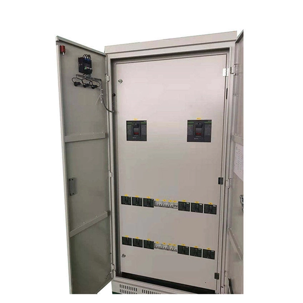
Abstract:The design, installation, and protection of wire and cable systems in substations are covered in this guide, with the objective of minimizing cable failures and their consequences. In modern electrical systems, cable distribution boxes (also known as electrical distribution boxes or distribution boxes) play a crucial role as the key hub for managing, distributing, and protecting circuits. Whether it is residential buildings, commercial facilities or industrial sites, the. The power demanded in electricity systems also determines the cable cross-section and properties as well as the current to be transferred. In case of high power use, to meet the demand of currentAnd in order for the current to be carried at the demanded high powers to be met, the method of parallel. A distribution box is the heart of any electrical system. It takes the incoming power and safely distributes it to different circuits throughout your building. Whether in a home or an industrial facility, this box keeps your electrical setup organized, functional, and efficient. However, the key to. Distribution Board or DB is an electricity supply system or a common enclosure that distributes the electrical power feed into subcircuits. Armored Cable (Type AC). Armored cable is an assembly of insulated conductors, 14 AWG through 1 WG, wrapped with waxed paper. The conductors are contained within a fl exible spiral metal (steel or al minum) sheath that the edges.
[PDF]

Part two of this series provides details on how to build the beam splitter. It is made from regular float glass without any coating. Watch part 1 if you want. A beam splitter or beamsplitter is an optical device that splits a beam of light into a transmitted and a reflected beam. It is a crucial part of many optical experimental and measurement systems, such as interferometers, also finding widespread application in fibre optic telecommunications. a laser beam) into two (or sometimes more) beams, which may or may not have the same optical power (radiant flux). One beam is typically reflected while the other is transmitted. The ratio of reflected to transmitted light can vary based on the design of the beam splitter. Types of Beam Splitters: Cube Beam. The SPIE Digital Library offers a wide range of resources on beam splitters, focusing on their design, applications, and performance across various optical systems. The library includes research papers, conference proceedings, technical articles, and book chapters that cover both theoretical and. Beamsplitters are optical components used to split incident light at a designated ratio into two separate beams. Beamsplitters are often classified according to their construction: cube or plate.
[PDF]

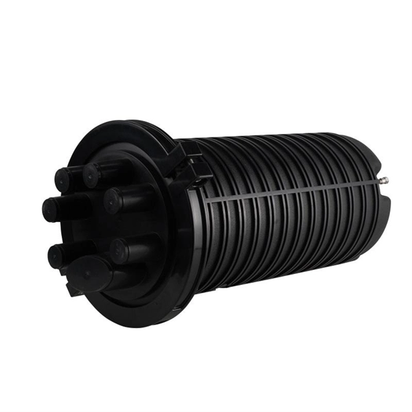
In this guide, you will find a chronological description of the fusion splicing process, the principal technical standards, and answers to the real-life questions network engineers and procurement teams may have. In this guide, we cover the basics of fiber optic splicing, how to perform splicing using two different methods, and finally some best practices to perform good fiber splicing. What is Fiber Optic Splicing and Why is it Needed? – #1. Use and Maintain Your. This Geoschematics drawing remains easy to read despite containing more than 2000 fibers and 500 splices. Splice Diagrams or Matrices capture an electric or optical network inside a location – documenting cables, ported equipment, and connections. Splices are fiber-to-fiber, port-to-fiber and. This guide will walk you through the complete process of fiber optic splicing—covering each step in detail so you can deliver a clean, professional splice every time. Before jumping into the physical steps, it's important to understand the two primary methods of fiber splicing: fusion splicing and. Page 1 The FOSC 450 fiber optic splice closures use compressed-gel cable seals to environmentally seal fiber cable splice points. FOSC 450-ab-c-dd-e-fgh The maximum single splice capacity of the FOSC 450 B6 closure is a = Closure size 144 with 24 splices stored on six trays. Therefore, we will also touch on cost factors, risk management, and best practices in.
[PDF]

Buy Panduit LabelCore Fiber Optic Cable Identification System Self-Laminating Laser/Ink Jet Labels at SHI. See detailed specifications and benefit from expert support. Shop IT hardware and software products with SHI now!. Indoor & outdoor fiber cable high visibility markers, id labels, printers, warning signs & posts, cable id sleeves and more for fiber optic applications. Check each product page for other buying options. Need help? Explore write-on fiber optic cable tags with self-laminating protection. Keep your cables organized and clearly labeled with writable identification solutions. The Multilink cable markers utilize a simple and quick installation that allows the installer to simply wrap the marker around the selected cable without the need for special tools or adhesives. The UV stabilized body will not degrade in outside applications and a variety of colors allows easy. According to research conducted by industry experts that shows network failures cost businesses the equivalent of five thousand dollars per minute. If technicians aren't able to quickly recognize the correct cable, these minutes can add up quickly. The TIA/EIA-606-A standard has created a unified system that specifies a "common" method of labeling the complete telecommunication infrastructure. PANDUIT Labeling Software packages include all label formats for quick and.
[PDF]
Fiber optic splicing is the process of joining two fiber optic cables together so that light signals can pass with minimal loss or reflection. Splicing is typically required during cable installation, maintenance, or network expansion. Another method of connecting optical fibers is termination or connectorization, which consists of processing the end of a fiber optic bundle so that it can be connected to other fibers or devices through fiber optic. When deploying fiber optic cabling, one of the most critical decisions is how to terminate the fiber—either by splicing or using connectors. Both techniques have their advantages and are suited for different applications, but understanding which method to use can greatly impact the network's. Fiber optic splicing, crucial for maintaining seamless connectivity in modern communication networks, primarily uses two methods: fusion splicing and mechanical splicing. Fusion splicing provides a low-loss, highly reliable connection by melting and fusing fiber ends, making it ideal for long-haul. As fiber optic connections become increasingly mainstream, the need to connect fiber optic cables to one another — or splicing — is also on the rise. Get the wrong connector type, the wrong polish, or skip proper fusion splicing technique—and you're looking at elevated signal loss, increased back reflection, and a.
[PDF]
