
The three primary types of fiber optic cable are single-mode fiber (SMF), multimode fiber (MMF), and plastic optical fiber (POF), each designed for specific applications based on distance, bandwidth, and cost considerations. Fiber optic cables transmit data as light, enabling faster and more reliable communication than traditional copper wires. Unlike copper wires, which are limited by lower data transmission speeds, shorter transmission distances, and higher susceptibility to electromagnetic interference, fiber optic cables offer unparalleled performance and can. While copper-based solutions (such as Cat5e/Cat6 for twisted pair or RG-6 for coaxial) have long served as workhorses for local and broadcast networks, fiber optic cable have seen explosive growth over the last decade. You'll learn what sets these cables apart, when to use each type, and how to avoid common installation mistakes. Whether you're. There are three main types of fiber optic cable. These are single-mode, multimode, and plastic optical fiber. Each type is good for different uses. Single-mode fiber sends data far away. The choice of fiber optic cable depends on the specific needs of the application, as well as the.
[PDF]
Splicing allows you to restore or expand fiber networks while maintaining signal integrity. When done right, splicing ensures minimal loss and long-lasting performance. This is where fiber optic cable splicing—the process of creating a permanent, high-performance join between two fiber ends—becomes critical. For network managers and technicians, a poor splice can lead to significant signal degradation, network downtime, and costly troubleshooting. At Turn-Key. To begin, the standard definition of splicing in optical fiber is joining two fiber optic cables together. The other, more common, method of joining fibers is called termination or connectorization. Splicing is most commonly used in the field but has application in cable assembly houses. Whether repairing a broken cable or extending a fiber run, fiber optic splicing ensures light signals travel. Whether you're installing new cables or repairing damaged ones, splicing techniques play a vital role in maintaining signal integrity. Choosing the right method affects performance, cost, and long-term durability. In this blog, we'll explore the main types of fiber optic splicing techniques, their. Joining two optical fibers at the right place so that light can be transmitted through them with minimal loss and reflection is known as splicing. Fiber optic splicing is done through two main methods. In fusion splicing, the ends of the fibers are welded together with heat. This guide will walk you.
[PDF]

The cost to install fiber optic cable ranges from $1. 50 to $42 per foot, with installation costs accounting for 60-80% of total project expenses. According to the Fiber Broadband Association's 2025 report, median costs are $8 per foot for aerial builds and $18 per foot for. Fiber optic cable installation costs between $1,500 and $7,000 for your home, with prices varying by cable length and installation method. The installation type you choose and the layout of your property determine the total labor and materials needed for your project. You should account for permit. The initial cost of installing fiber optic cables can vary depending on the chosen installation method and specific project requirements. Total Project Costs: For commercial installations, expect costs ranging from $5,000 to $20,000 per mile for underground projects and from $40,000 to $60,000 per. Homeowners and businesses typically pay for fiber optic cable installation based on distance, conduit needs, and labor. The main cost drivers include material type, run length, trenching or aerial work, and any required permits or inspections. This comprehensive guide breaks down the factors influencing pricing, average expenses, and tips to get the best value in 2025. Clear insights help make informed decisions without unexpected surprises. Let's start by getting a better idea about the material cost. Understanding the fiber cable cost per foot is crucial before.
[PDF]
This article is about the Internet Outages Map, which provides a visualization of global internet health over the last 24 hours. It also includes information on how to use this map and what data it collects, as well.
[PDF]

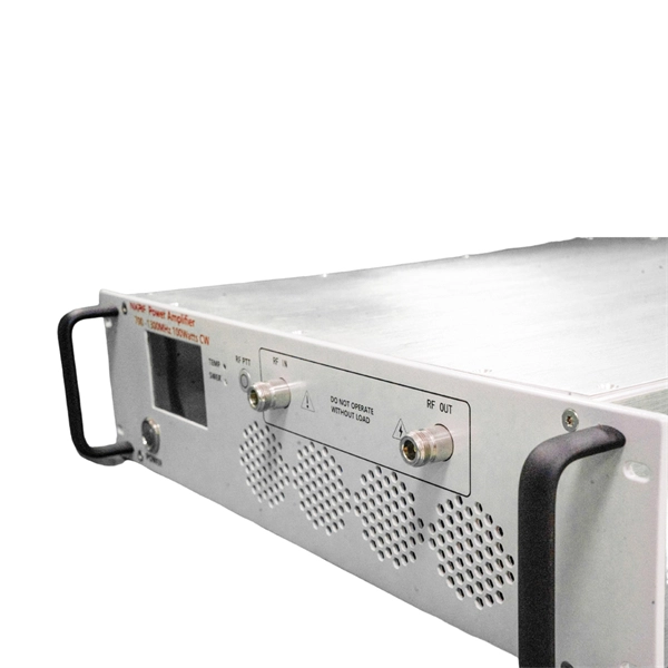
Will fiber optic cables replace coaxial cables entirely? The short answer is: not entirely. In this article, we'll help you understand where each. Fiber optic cables and coaxial cables have something in common; both of them can provide homes and businesses with tv, phone, and Internet service. Cables. Optical fiber can carry analog RF signals from antenna to receiver with far less loss than coaxial cables. It's not unusual in engineering to find solutions to long-standing problems leveraging apparently unrelated technologies. But these signals have a fatal flaw: when transmitted through traditional copper coaxial cables, they degrade and distort rapidly over distance. It's like shouting into a long metal pipe—the sound that comes out the other. Seamless Radio Frequency Signal Transmission over Optical Networks RF over Fiber (RFoF) technology enables the transmission of radio frequency (RF) signals over optical fiber instead of traditional coaxial cables. This method combines the advantages of fiber optics—such as low signal attenuation.
[PDF]
This article will guide you through the process of troubleshooting fiber optic connections, with a focus on ensuring proper TX and RX alignment and how to correctly switch patch cables to resolve issues. Proper connection of fiber optic cables is essential to harness these benefits fully, as even minor errors can lead to significant performance issues like signal loss. When issues like signal loss, slow speeds, or intermittent connectivity arise, systematic troubleshooting is key. This guide will walk you through diagnosing and resolving common. The process to connect fiber optic cable to router requires careful attention to detail, but I'll walk you through every critical step with the precision and clarity you deserve. This comprehensive guide combines industry standards with field-tested practices to ensure you achieve a rock-solid. Fiber optic cables are widely used in modern networks for their high-speed data transmission capabilities and resistance to electromagnetic interference. However, like any other networking technology, fiber optics can encounter issues that disrupt communication. One of the most common problems in. Fiber optic internet delivers blazing-fast speeds and reliable connectivity, making it a top choice for modern homes and businesses. Their ability to transfer large amounts of data at lightning speed makes them a go-to for efficient communication. Knowing how to avoid signal loss in.
[PDF]
Choose an SFP module based on the fiber optic cabling that will be connected to the network switches. In addition, fiber cables can transmit data over several kilometers without signal degradation, making them ideal for connecting switches in large campus networks and between different buildings. As they do not emit electromagnetic signals, they're difficult to tap and secure against eavesdropping. Most modern SFP transceiver modules. Hi Experts, I have a basic knowledge of network and need some help. I need to connect 4 Floor Building with 4 Cisco 2960 - 48 ports switch each other and it needs to be through a fiber. So all PCs connected to each switch would reach the LAN/WAN from the other switch. (attached is the image here. Fiber optic cabling is increasingly used to connect network switches and other datacom equipment, especially in long-distance and mission-critical applications. Fiber provides: Increased internet signal bandwidth. Another way is to put a switch at Location B and interconnect using SFP modules. But is it possible to connect AB and BC cables using fiber optic patch cords ? Will it work in this fashion ? If this can work, I. We can use either the cat6 cable or fiber optical cable to link two network switch. One of the advantages of fiber optical cable is its fast speed. In this video, you will see how to link two network ports together to achieve 2G bandwidth between the switches. You even can connect more.
[PDF]

Extending the fiber through the box makes use of a cable entry gland. Fasten the cable to the clamps or ties to assure the cable is immovable. Cable must be properly minimum radius (usually ≥30mm for standard fiber). Remove the cable jacket and buffer coating material. Thus, a fiber termination box is used to terminate the optical fiber cables in the field and connect them to the pigtail by splicing. After an optical cable arrives at the user's end, it is fixed in the terminal box. Fiber adapters: These are used to connect the fiber optic cables to the fiber termination box and should comply with industry. Teleweaver emphasizes the importance of choosing the right FTB based on specific requirements. The common types include: Wall-Mounted FTBs: Ideal for residential and small-scale applications, these are compact boxes designed to be mounted on walls for easy access and space-saving cable management. To address this problem, the fiber termination box (FTB) was created to protect the fragile fiber terminals and provide a simple and clear way to manage the incoming and outgoing cables. more Order it here: https://www. This video shows you a step-by-step instruction on how to terminate 12 strands single mode fiber cables, splicing them with fiber optic pigtails.
[PDF]

This OSHA-format Fiber Optic Cable sign makes your Electrical message clear to employees, visitors and inspectors. Sign design conforms to OSHA 29 CFR 1910. 145 standard for header style, text format and header color. Designed to alert workers to buried fiber optic or communication lines, this triangular marker delivers 360° visibility and rugged performance in all weather conditions. Add your own custom warning text, company name, and emergency contact information. The image in the builder is for preview. Buried detectable & non-detectable warning tapes, high visibility reflective laminated labels & flexible line marker posts, soil markers, domed posts. Clearly identify vulnerable underground assets with durable ground-level markers. US-made OSHA WARNING safety sign is UV, chemical, abrasion and moisture resistant. Help prevent dig-ins with a Fiber Optic Warning Sign. A single dig-in can disrupt vital –and often life threatening communication services. • Find both in-stock signs and easy to customize templates. • Durable fiber optic signs are printed using 3M's matched component system for maximum outdoor. This article focuses on the selection decision-making problem of two types of Fiber Optic cables in optical network design. It systematically sorts out the structure, classification, and performance differences of the two types of Fiber Optic cables, and combines industry standards, market data.
[PDF]

Main cost drivers include cable grade (indoor vs outdoor, armoured), distance, and labor for trenching, splicing, and termination. This guide presents ranges in USD and practical price estimates to help budget planning. Indoor OM3/OM4 vs outdoor armoured increases price. For fiber cable materials only, expect $0. 52 per foot for wholesale bulk purchases, or $1 to $6 per foot at retail. The wide price range reflects differences in fiber strand count, outer jacket construction, and application type. 13 per foot. Buyers typically pay for fiber optic cable by length, fiber type, and installation complexity. Whether you're planning a national fiber rollout or sourcing cables for enterprise infrastructure, understanding how fiber optic cable pricing works can help you budget more effectively and make better. Owners and buyers often pay for fiber optic cable by the meter, plus labor, connectors, and installation. First and foremost, fiber cables are either singlemode or multimode. Singlemode cables with a small core diameter of 9 microns use high-power laser light sources to support high-speed.
[PDF]

A massive outage has been reported in the Los Angeles area on Father's Day after internet and cable provider Spectrum linked the issue to "criminal acts of vandalism. " "We are currently working on a Fiber cut affecting the Los Angeles area. We are sorry for the inconvenience this. SPARTANBURG COUNTY, S. (WSPA) – Spectrum is offering $25,000 for information leading to the arrest of a suspect accused of cutting and damaging cable lines. Officials said a fiber optic line was intentionally cut, resulting in temporary outages in parts of Spartanburg County, including Inman. Authorities in Spartanburg County, South Carolina, are searching for a vandal who they say cut fiber optic lines Sunday morning. Spectrum says the lines were intentionally cut, resulting in a temporary outage for residents and businesses. In a statement, a Spectrum spokesperson writes, "Criminal. ©2025 NewsBreak. The incident is being treated as an attempted theft. 'The Free Press' reporter Madeleine Rowley discusses the reality behind President Biden's broadband internet project on 'The Bottom Line. Domestic Violent Extremists (DVEs) have increasingly discussed targeting. Several Spectrum lines cut and laid out as repairs continue to restore services throughout the Long Beach area in Signal Hill Thursday, June 19, 2025. Photo courtesy of Spectrum. An internet outage across large parts of Long Beach was caused by someone who intentionally cut fiber optic lines “in a.
[PDF]
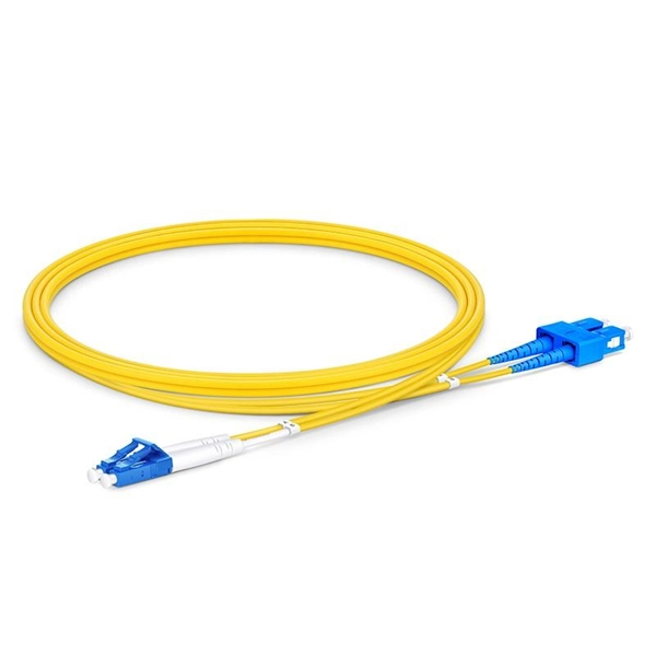
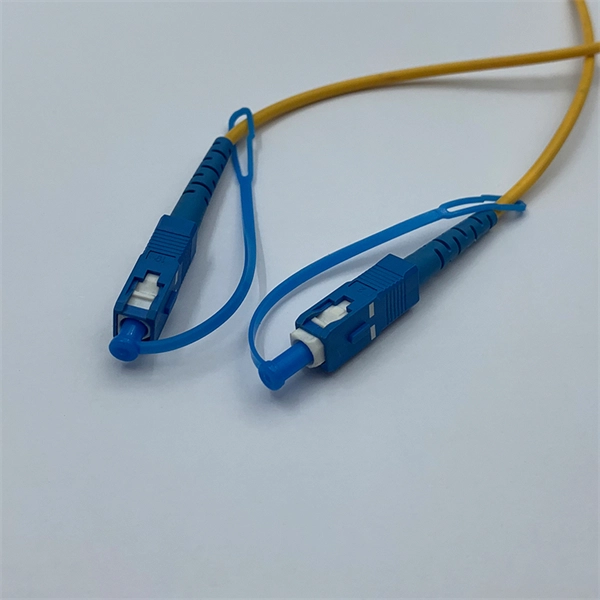
The fiber connector types, sometimes referred to as terminations, link fiber optic cables together through terminals, switches, adapters, and patch panels, by bridging the gap between their internal glass fi.
[PDF]
This comprehensive guide will delve into the best practices for cable removal, the benefits of maintaining a clean cable environment, and step-by-step instructions to ensure the process is efficient and compliant with industry standards. Every new installation means an increased number of low voltage cables that are cut and left in ceilings, floors, and walls. From a tenant or building owner's point of view, removing abandoned cable has. Effective cable removal ensures safety, optimizes performance, and prepares the infrastructure for future upgrades. Before beginning any installation, safety. Fiber-optic cables are the backbone of modern connectivity—powering 5G networks, global internet backbones, and data center interconnections with near-light-speed data transmission. While these cables are engineered for durability (with some rated to last 25+ years), they are not invulnerable. Even. Here are 5 vital rules for staying safe when you're working on fiber optic cables. Know the standards that apply to your work Whether you're installing new fiber optic cables or troubleshooting and repairing an existing fiber network, a working knowledge of the regulations that apply to your. In outside plant fiber optic installations, the biggest cause of network failure is likely to be electronic problems or, if it's in the cable plant, what is usually called “backhoe fade” for buried cables and “target practice” for aerial cables, both of which are self-explanatory.
[PDF]

