Optical modules —including SFP, QSFP, and CWDM series —serve as the core components enabling this high-speed, high-bandwidth, and long-distance connectivity. Without them, even the most powerful GPU clusters would be bottlenecked by network limitations. High-Speed Data Transmission. Various versions of calculations regarding the ratio of optical modules to GPUs circulate in the market. The main reason for the inconsistency in these numbers is the varying usage quantity of optical modules in different networking architectures. The actual number of optical modules used primarily. There are multiple methods on the market for calculating the ratio between compute optical modules and GPUs, resulting in different outcomes. NVIDIA ® LinkX ® Optics Ethernet transceivers are used to create high-speed, 100G–400G links supporting every configuration, reach, and speed in networks requiring detachable optical connectors. LinkX transceivers are.
[PDF]

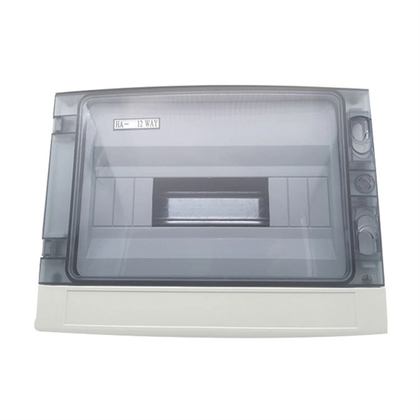
Welcome to our channel! In this video, we'll walk you through the process of wiring a home distribution box with a detailed connection diagram. What is Distribution Board? Distribution board. These smaller breaker panels, also known as sub-distribution boards, are commonly used to provide power to secondary circuits within a building. Understanding the components and wiring configuration of an electrical sub panel is essential for safe and efficient electrical installations. In this. Primary distribution systems consist of feeders that deliver power from distribution substations to distribution transformers. A feeder usually begins with a feeder breaker at the distribution substation. Many feeders leave substation in a concrete ducts and are routed to a nearby pole. This breaker must be compatible with both your main system and the additional connections. Typically, a 60-amp or 100-amp breaker will be suitable, depending on the load requirements. It includes isolator, RCCB (Residual current circuit breaker) or RCD (Residual-current device) devices, protective fuses or MCB's (Miniature Circuit Breaker).
[PDF]

This document provides direction on properly identifying the ribbon and individual fiber in the AFL Wrapping Tube Cable. Depending on fiber-count, ribbon band-marking (striping) and binder group count will differ. The number of optical cores in an optical fiber is the total number of equipment interfaces multiplied by 2, plus 10% to 20% of the spare quantity, and if the communication mode of the equipment has serial communication and equipment multiplexing, you can reduce the number of cores. The number of. A fiber optic patch panel is a critical piece of equipment used to organize, manage, and connect fiber optic cables within a network. It serves as a central hub where multiple fiber optic cables can be routed, terminated, and interconnected to various network devices such as switches, servers, or. Fiber optic cables are essential to modern networks, enabling high-speed and reliable data transmission. Among their many features, the number of fiber cores directly affects data capacity and network performance. Understanding this key aspect is crucial for making the right choice. This post will guide you through understanding fiber optic cores and selecting the perfect cable for.
[PDF]

In this guide, you will find a chronological description of the fusion splicing process, the principal technical standards, and answers to the real-life questions network engineers and procurement teams may have. In this guide, we cover the basics of fiber optic splicing, how to perform splicing using two different methods, and finally some best practices to perform good fiber splicing. What is Fiber Optic Splicing and Why is it Needed? – #1. Use and Maintain Your. This Geoschematics drawing remains easy to read despite containing more than 2000 fibers and 500 splices. Splice Diagrams or Matrices capture an electric or optical network inside a location – documenting cables, ported equipment, and connections. Splices are fiber-to-fiber, port-to-fiber and. This guide will walk you through the complete process of fiber optic splicing—covering each step in detail so you can deliver a clean, professional splice every time. Before jumping into the physical steps, it's important to understand the two primary methods of fiber splicing: fusion splicing and. Page 1 The FOSC 450 fiber optic splice closures use compressed-gel cable seals to environmentally seal fiber cable splice points. FOSC 450-ab-c-dd-e-fgh The maximum single splice capacity of the FOSC 450 B6 closure is a = Closure size 144 with 24 splices stored on six trays. Therefore, we will also touch on cost factors, risk management, and best practices in.
[PDF]
The procedures of testing switchgear, instrument transformers and relays are explained in detail. The close and trip, indication and alarm circuits for variety of circuit breakers indicating ferrule numbers are al.
[PDF]

6 core Fiber Optical Splicing With 24 Port LIU || Full Installation || Beginner Watch this video Fiber optic splicing is the process of joining two fiber optic cables together to create a conti. more. In this article, we'll explain how to connect multiple Ethernet switches using fiber optic cables and the equipment required for this to work. Network topology refers to the way in which the links and nodes of a network are arranged in relation to each other. Simply put, it defines how network. Choose an SFP module based on the fiber optic cabling that will be connected to the network switches. SFP transceiver modules almost always require two fiber optic cable strands. Most modern SFP transceiver modules. Most modern fiber-enabled network switches require an SFP transceiver module featuring a duplex (two strand) multimode OM3 or duplex single mode OS2 connection with LC connectors. Direct attach cables with pre-terminated SFP connections may also be used. Download the Application PDF SFP transceiver. This article will guide you through the necessary tools, materials, and methods on how to connect fiber optic cables effectively, ensuring you achieve optimal performance from your fiber optic network. These diagrams help engineers plan infrastructure for residential and commercial buildings. By using light signals, fiber optics provide faster speeds and better reliability than.
[PDF]
The term host bus adapter (HBA) may be used to refer to a interface card. In this case, it allows devices in a Fibre Channel to communicate data between each other – it may connect a server to a switch or storage device, connect multiple storage systems, or connect multiple servers. Fibre Channel HBAs are available for, computer architectures, and buses, i.
[PDF]

Download the most popular free Fiber optic cable card vectors from Freepik. Explore AI-generated vectors and stock vectors, and take your projects to the next level with high-quality assets!. Fiber U is the free online learning website of the FOA - the Fiber Optic Association, the international professional association and certifying body devoted to the development of a skilled workforce in fiber optics and telecommunication. Here you will find free online self-study courses, tutorials. Free online self-study programs on many fiber optics and cabling topics are available free at Fiber U, FOA's online web-based training website. FOA Reference Books (Available Printed or eBooks) The fiber book is available in Spanish and French as well as English. Click on any of the books to learn. Copyright © 2010- 2026 Freepik Company S. Dura-Line Academy and Broadband Nation are offering free training on fiber basics. Sign up for free here and gain access to all three 10-minute mini courses: Fiber-Optics 101: Learn the basics about fiber-optics theory, along with the different types of fiber and cables. FOA is also an internationally recognized certifying body for fiber optics.
[PDF]
Line cards are field-replaceable units (FRUs) that you can install in the line card slots on the front of the switch chassis. Cisco ® Catalyst ® 9400 Series switches are Cisco's lead modular enterprise access switching platform and as part of the Catalyst 9000 family, are built to transform your network to handle a hybrid world where the workplace is anywhere, endpoints could be anything, and applications are hosted all. The Cisco® Digital Network Architecture (Cisco DNATM) with Software-Defined Access (SD-Access) is the most advanced network fabric to power customer business. Cisco DNA is an open and extensible, software-driven architecture that accelerates and simplifies your enterprise network operations. The. Get Advice: Live Chat | +1-626-655-0998 | Email Check D-Link Core Switch Line Cards price and buy one with best discount. Fast shipping and free tech support. Built upon the foundation of the Catalyst 9000, the Catalyst 9600 Series offers scale and security when always-on is a. If you are installing line cards released after Junos OS Release 14. 1, ensure that the Switch Fabric module (SF module) EX9200-SF2 is installed in the switch chassis.
[PDF]

Fiber optic network diagrams represent the architecture and connectivity of fiber optic systems, and their design philosophy integrates technical, functional, and conceptual aspects. The diagrams abstract complex details of fiber optic systems to make them. Fiber optic network design refers to the specialized processes leading to a successful installation and operation of a fiber optic network. It includes first determining the type of communication system (s) which will be carried over the network, the geographic layout (premises, campus, outside. A fiber optics network diagram illustrates how high-speed data travels from an internet service provider to end users. These diagrams help engineers plan infrastructure for residential and commercial buildings. What is fibre network mapping? Fibre network mapping is a critical process in the planning, deployment, and management of fibre optic networks. I'm needing symbols for common fiber optic components, cables, connectors, backbone ports, etc. Can anyone help me out? Some examples of a diagram would also help. 10-27-2018 01:41 AM Do you know if there's some symbol standard. Definition: Fiber optic cable is also called the “ Optical Fiber Cable “, and it is simply Ethernet networking cable that contains the multiple optic fibers, and they allow to transmit data with massive volume. Main goal of designing the optical fiber cable is to offer ultra performance data.
[PDF]


