
This blog article entry considers the merits of choosing which of various low loss RF coaxial cables to use for IoT, LTE or LORA wireless applications where an external antenna is used to connect to router, gateway or terminal. The choice looks deceptively simple—pick a length, screw it on—but RF engineers know the truth: every extra meter quietly eats away at your link budget, especially once you cross 2 GHz. It's not just about length; the cable type, connector quality, and even mounting environment make a measurable. Audio generated by DropInBlog's Blog Voice AI™ may have slight pronunciation nuances. In this article, we will consider cables such as RG174, RG58, RF195. The cheap connectors have inferior dielectric between the poles as well as poorer grades of metal. The dielectric won't handle high power (KW range) as well and the center pin can more easily shift causing impedance problems if they are moved frequently. RF connectors are usually used with coaxial cables. They are designed to maintain the shielding that the coaxial design offers. The better and newer. Besides the wide range of RF connectors, Telegärtner also provides a considerable range of suitable coaxial low loss cables. Using this one-stop shopping option at Telegärtner makes your purchasing process even more efficient. The main use of low loss cables are all kinds of wireless applications.
[PDF]

Explore the precision, applications, and design principles of beam splitters, essential for advancements in scientific research and technology. Beam splitters are integral optical components that divide a beam of light into two or more separate beams. There are two basic types of beamsplitters: Non-polarizing beamsplitters (NPBS): This type of splitter is used to divide (split) a beam into two beams and each output beam is a fraction of the incoming beam regardless of the polarizations. Non-polarizing beamsplitters are used in a variety of. 📦 For purchasing, use the RP Photonics Buyer's Guide for beam splitters. It provides an expert-curated supplier directory, buyer-focused technical background information, and structured selection criteria to support professional procurement decisions. What are Beam Splitters? A beam splitter (or. As a basic and important link in on-chip photon propagation, beam splitting is of great significance for the efficient utilization of sources and the compact integration of optoelectronic devices. It is widely used in power splitting, polarization separation, wavelength division multiplexing and. The SPIE Digital Library offers a wide range of resources on beam splitters, focusing on their design, applications, and performance across various optical systems. The principle of beam splitting is based on the manipulation of light waves using various optical materials and coatings. Their precision and versatility make them.
[PDF]

This paper is focused on the performance analysis of protection mechanisms utilized in common wavelength division multiplexing-based passive optical networks. Wavelength division multiplexers are fundamental to the functioning and performance of integrated photonic circuits, with applications ranging from optical interconnects to sensing and quantum technologies. Current solutions are limited by trade-offs between channel spacing, crosstalk, insertion. Wavelength division multiplexing (WDM) is a technology for increasing the transmission capacity of optical fiber communications by sending multiple data channels simultaneously through a single fiber, each on a different wavelength of light. The main aim of the proposed research is providing an option of comparing different traffic protection scenarios for advanced optical. Herein, an attention-grabbing and up-to-date review related to major multiplexing techniques is presented which includes wavelength division multiplexing (WDM), polarization division multiplexing (PDM), space division multiplexing (SDM), mode division multiplexing (MDM) and orbital angular momentum. The journey of optical multiplexing began in the 1970s with the introduction of Wavelength Division Multiplexing (WDM), which revolutionized the capacity of optical communication systems. The primary objective of optical multiplexing has been to maximize the utilization of available bandwidth in.
[PDF]
If you are responsible for cable management in a commercial or industrial setting, you know how important it is to keep your wiring organized and secure. Without an efficient cable management system, you coul.
[PDF]

The transmitter takes an electrical input and converts it to an optical output from a laser diode or LED. The light from the transmitter is coupled into the fiber with a connector and is transmitted through the fiber optic cable plant. The signal is produced by a crystal oscillator made from quartz. The quartz keeps the signal on frequency. Two other stages include a driver and a power amplifier. In order to send information, you have to modulate the RF carrier. This usually involves a process known as modulation, where the input signal is combined with a carrier signal to create a new signal that can be. Digital coherent optical systems use advanced digital signal processing and modulation techniques at the transmitter and receiver. Therefore, we begin this chapter by reviewing the fundamentals of digital communications, including principles of modulation, channel modeling, and detection. After. Analog optical transmitters and receivers are designed to meet the evolving needs of high-throughput radio frequency (RF) systems across various industries. AOwave analog optical modules support next-generation analog optical links up to the Ka-band, targeting both terrestrial and space. The essential function of a radio transmitter architecture is taking low-frequency information, the baseband signal, and transferring that information to much higher frequencies by superimposing the baseband signal on a high-frequency carrier, i. This could be done by slowly varying.
[PDF]

IEC fiber connector standards establish the global specifications for connector geometry, mating interfaces, optical performance classes, and mechanical testing across all fiber network environments. Optical connectors are used to connect optical devices to other optical devices or systems. However, each connection introduces a certain amount of insertion and return loss that. Connectors play an important role in Enterprise network architecture. They give you the power to add, drop, move, and change the network. is a small cylinder used to mount. The Fischer FiberOptic Series offers robust and faultless optical performances in any conditions. Combined with easy use, cleaning and maintenance. Tested for harsh and extreme environments (Norm IEC 61753-1 Cat. These standards ensure that passive fiber-optic components remain interoperable, stable, and. designed for diverse fiber optic applications. But what exactly sets a fibe optic connector apart in terms of its merits? The primary purpose of a fiber optic connector is to terminate the ends of fiber optic cables, ensuring they can be int rconnected reliably with minimal optical loss. After. Fiber optic technology is used in ever-increasing applications due to its inherent advantages (lower weight, EMI/RFI immunity, higher bandwidths and distances) over copper. There are many.
[PDF]

Based on analysis on the dispersion of the optical system of a MEMS-based VOA, we provide a method to reduce the WDL significantly with minor revision on the end-face angle of the collimating lens. 📦 For purchasing, use the RP Photonics Buyer's Guide for variable optical attenuators. It provides an expert-curated supplier directory, buyer-focused technical background information, and structured selection criteria to support professional procurement decisions. Variable optical attenuators are. An optical attenuator, or fiber optic attenuator, is a device used to reduce the power level of an optical signal, either in free space or in an optical fiber. The basic types of optical attenuators are fixed, step-wise variable, and continuously variable. Optical attenuators are commonly used in. Applications in broadband optical fiber communication system need variable optical attenuators (VOAs) with low wavelength-dependent loss (WDL). What Are Fiber Optic Attenuators? Fiber optic attenuators, also called optical attenuators, are passive. Optical attenuators are categorized based on their attenuation mechanism and adjustability: Fixed Optical Attenuators: These attenuators reduce the signal power by a predetermined value and are used in applications where a constant level of attenuation is required. It works by dissipating a portion of the optical power passing through it, thereby lowering the overall power level. Fiber optic attenuators.
[PDF]
The Patch and Splice Combo Patch Panel is designed to allow both the patching and splicing of fiber optic cable all in one unit; these particular units have fiber termination panels in the upper slide out shelf and splice trays in the lower shelf. NG4access ® Cabled Modules available in all module sizes and fiber counts up to 864 fibers NG4access ® Splice Tray Four sizes of interchangeable Propel fiber pass-through adapter packs provide the breadth of capabilities for virtually any configuration. Four sizes of interchangeable Propel fiber. Cisco is introducing a family of fiber management solutions with a debut of SMF and MMF patch panels. The panels will enable Cisco's customers to facilitate breakout connectivity agnostic of the data rate. The Cisco® solution of panel and cable assemblies offers versatile solution for any breakout. Our fiber patch panel offers options for flexible cable management and seamless integration with various cassettes and fiber optic accessories. Allowing full front access for network. Foss FP-series front patch panels are made with the highest accuracy for precise fitting. All panels are tested according to both our own quality measures and international standards before they are sent to customers. Similarly, the ABS High Density Shelves bring a new level of access, convenience, and security to its Fiber Splice Shelf, enabling quick and easy fiber splicing and connectivity for rack mount applications.
[PDF]

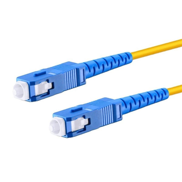
Of the more than a dozen types of fibre-optic connectors available, the four most commonly used today are LC, SC, FC, and ST. Fiber connector types LC, SC, FC, ST, MTP, and MPO are widely used in past and present. What are the differences between them? Who is the most popular one? Find the answer in the article. What is a Fiber Connector? The optical fiber connector is a kind of detachable passive optical component used. Fiber optic connectors are the unsung heroes of modern networking. They are small, often overlooked components, yet they are essential for ensuring high-speed, low-loss, and reliable optical transmission. In addition to serving the same general function, the four connectors differ in size, locking mechanism, and best applications. The following guide systematically describes. Choosing the right connector for an optical link is one of those small decisions that has outsized effects on installation density, reliability, and long-term maintenance. broadband connection is available everywhere. Its. Optical fiber terminations are the mechanical and optical interfaces that connect fiber cables to equipment, patch panels, and network hardware. They directly affect insertion loss, return loss, reliability, and long-term network stability. In this guide, we break down the most common optical fiber.
[PDF]

As Armenia transitions to renewable energy (15% of its power already comes from solar!), these cabinets act like Swiss Army knives for electricity—versatile, compact, and ready for action. Here in Triangle Connected Technologies we do Electrical Engineering and consulting. We are a systems integration company that provides exceptioanal solutions for your needs. We are expertise in Electrical, Low Current Systems and KNX Smart Home automation systems design, supply, installation and. Who makes energy storage enclosures?Machan offers comprehensive solutions for the manufacture of energy storage enclosures. We have extensive manufacturing experience covering services such as battery enclosures, grid energy storage systems, server cabinets and other sheet metal enclosure OEM. transforming Armenia"s energy landscape. But instead of unloading goods, it stores nough energy to power 300 homes for utdoor Cabinet Type Energy Storage System. The outdoor cabinet energy storage system, is a compact. This scenario explains why the smart energy storage cabinet solution is becoming the talk of Yerevan's tech circles. Cooperate with solar panels to form an. Huijue Group"s Industrial and commercial distributed energy storage, with independent control and management of single cabinets, has functions such as peak shaving Lithium Battery Energy Storage Cabinet. Energy Storage System. :-20°C~ 60°C.
[PDF]

As an essential component of optical fiber communication, optical modules are optoelectronic devices that facilitate the conversion between optical and electrical signals during the transmission process. Operating at the physical layer of the OSI model, optical modules are core devices in optical. An SFP (Small Form-factor Pluggable) is a compact, hot-pluggable transceiver module that allows networking equipment — including switches, routers, servers, and media converters — to support different physical media, such as optical fiber or copper, without replacing the host hardware. This modular. Analog Devices' optical networking solutions address a wide range of applications in data center, enterprise, and telecom markets. They enable power efficient and small form factor optical modules to support network traffic and bandwidth growth driven by the digital economy, social media, streaming. Everything you need to build an optical network from end-to-end. Thin-film filter and PLC based AWG for multiplexing, a full suite of components for optical amplification use, optomechanical or MEMS-based switches for protection or surveillance application, Tap PD for power monitoring and VOA for.
[PDF]

This guide will explain their functions, discuss the role of single-mode LC connectors in modern fiber optic systems, and present the logic for their adoption on a broader scale. Proper connection of fiber optic cables is essential to harness these benefits fully, as even minor errors can lead to significant performance issues like signal loss. This article will guide you through the necessary tools, materials, and methods on how to connect fiber optic cables effectively. Fiber optic internet delivers blazing-fast speeds and reliable connectivity, making it a top choice for modern homes and businesses. In this guide, we'll walk you through how to. In this article, we'll explain how to connect multiple Ethernet switches using fiber optic cables and the equipment required for this to work. Network topology refers to the way in which the links and nodes of a network are arranged in relation to each other. There are also fiber-to-fiber versions that translate between different fiber types, wavelengths, or distances. Common families support 10/100/1000 Ethernet and. This is where single-mode fiber optics comes in. Single-mode fiber is being viewed as the backbone of enterprise connections, and it is used to facilitate all 400G solutions and real-time AI solutions/applications, due to its ability to transmit data over long distances with minimal signal loss.
[PDF]
Follow the described steps to factory reset an IBM Brocade switch running FOS 7. Run firmwarecleaninstall on each CP or switch After firmwarecleaninstall, all passwords, such as root, admin, factory and user are cleared (set to the default value). Before installing a new software version and RCF files, you must erase the current switch configuration and perform basic configuration. Log in to the switch as an administrator. The system is halted flushing ide devices: hda Power down. Display information about switches in the fabric. Display how long the switch is running, number of connected users and the system load for the past 1, 5 and 15 minutes. Display or set date and time (This is Readonly if NTP is. This video will demonstrate clear procedure of an interface and ASIC counters on Brocade B-Series Switches and Directors Welcome to Dell Technologies Connectrix Brocade How To Series. WARNING: This is a.
[PDF]

