The primary problem encountered is signal loss, also known as attenuation. Attenuation can be due to absorption, scattering, or bending losses, affecting the quality and speed of data transmission. Attenuation in fiber optic cables is the reduction in signal strength during. To be able to judge whether a fiber optic cable plant is good, one does a insertion loss test with a light source and power meter and compares that to an estimate of what is a reasonable loss for that cable plant. The estimate, called a "loss budget" is calculated using typical component losses for. F iber optic networks rely on the efficient transmission of light signals to deliver high-speed data over long distances. However, various factors can cause signal degradation, leading to performance issues and reduced network reliability. Fiber optic signal loss, also known as attenuation, occurs. A significant signal loss in the optical fiber can cause unreliable transmission. How can we know the value of losses on the fiber link? Read on, this post will teach you how to calculate the losses in optical fiber and judge the fiber link performance. The uses various types of network cables, including multimode and single-mode fiber-optic cable. It can also break your connection. High attenuation makes your system not work well. You should fix it fast to get speed and stability back. > You can solve this with simple steps.
[PDF]

Compare fiber optic and copper Ethernet cables across speed, distance, cost, installation difficulty, and use case metrics. Use the interactive scenario selector to find the right medium for your specific network — all processed locally in your browser. PoE Required?. The core difference between fiber optic and copper cables lies in how they carry data. One uses light, the other electricity—and that distinction shapes everything from speed to signal integrity. Fiber optics transmit data as pulses of light through ultra-thin strands of glass or silica. Both technologies can deliver high-speed connectivity, but they behave differently under real-world constraints such as. However, the exponential growth in data demand has positioned fiber optic technology as the superior alternative for performance, scalability, and future-readiness. This article provides a detailed technical comparison between fiber optic and copper cables, offering a clear perspective for. Fiber optic tends to be the more premium solution, while copper wiring is far more common, but why is that? What are the differences between these two cable types, and why might you want to pick one over the other? Here's everything you need to know about fiber vs. copper cables, to help you pick. Several factors are converging to drive the switch from copper to fiber – and cost is a big one. A recent investor presentation by AT&T claimed that fiber was 35% less costly to maintain than copper.
[PDF]
An optical fiber is a cylindrical ( waveguide) that transmits light along its axis through the process of total internal reflection. The fiber consists of a core surrounded by a layer, both of which are made of materials. To confine the optical signal in the core, the of the core must be greater than that of the cladding. The boundary between the core and cladding m.
[PDF]

This guide explains fiber optic cable construction, the difference between tight buffer and loose tube structures, and compares eight common cable types used in data centers, enterprise networks, and FTTH deployments. The Fiber Optic Association, Inc. (FOA) was founded in 1995 to help develop the workforce to build the fiber optic networks to support a rapid expansion in communications and the Internet. The charter of the FOA was to promote professionalism in fiber optics through education, certification, and. 40. FO-VC2 JOINT USE - VERICAL MIDSPAN CLEARANCES 48. FO-GB GROUNDING AND BONDING 49. APPENDIX A - COVER SHEET / TOC 52. Building a fiber optic network is a highly technical yet vital process that enables communities and businesses to access high-speed, reliable fiber optic internet. From the initial site survey to the final fiber to the home (FTTH) connection, every stage requires careful planning, coordination, and. Fiber optic cables facilitate high-speed connectivity with significant advantages over copper wires, such as faster data transmission, greater bandwidth, and better security; single-mode fibers are ideal for long distances, while multi-mode fibers suit short-range communications. Proper fiber optic. Fiber optic cables come in many designs depending on where and how they are deployed. The method covers the steps from receiving the materials on the installation site and cable pulling as per the approved shop drawings.
[PDF]

A compilation of available thermal data in Spain, including thermal gradient, heat flow and other thermal indicators, and its interpretation are presented. A regional geothermal gradient map constructed on the basis of data from onshore and offshore oil wells, water wells and geothermal exploration work allows the definition of thermal gradients in the Alpine part of Spain but leaves uncovered the Hercynian part. For this, we have used refined heat producing elements (HPE) values to obtain new estimates of heat production rates in the. Geothermal represented 0. 5 % of the global renewable electricity market in 2022, generating 0. Geothermal energy has a high potential to supply the EU's district heating and cooling sector, while emerging technologies for higher temperatures and efficiency and for. Institute of Earth Sciences (C. Martí i Franquès s/n, 08028 Barcelona, Spain The north-eastern border of the Ebro foreland basin is characterized by relatively high elevation. the presence of Neogene to Present volcanism, and a high thermal gradient. These facts suggest that the area is. The analysis of a 24-year time series of Conductivity-Temperature-Depth (CTD) casts collected in the Balearic Channels (1996–2019) has allowed detecting and quantifying long-term changes in water mass properties in the Western Mediterranean. For the complete period, the intermediate waters have.
[PDF]
Polarization-maintaining fibers work by intentionally introducing a systematic linear birefringence in the fiber, so that there are two well defined polarization modes which propagate along the fiber with very distinct phase velocities. The beat length Lb of such a fiber (for a particular wavelength) is the distance (typically a few millimeters) over which the wave in one mode will experience a. OverviewIn, polarization-maintaining optical fiber (PMF or PM fiber) is a single-mode in which , if properly launched into the fiber, maintains a linear polarization during,. In an ordinary (non-polarization-maintaining) fiber, different polarization modes have the same nominal due to the fiber's circular symmetry. in such a fiber, or bending. Several different designs are used to create birefringence in a fiber. The fiber may be geometrically asymmetric or have a refractive index profile which is asymmetric such as the design using an elliptical as.
[PDF]

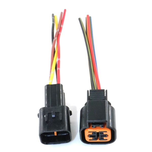
In this article, we will provide you with a step-by-step guide on how to install and remove fiber optic connectors properly. Step 1: Prepare the necessary tools and materials, including the fiber optic connector, cable stripper, fiber cleaver, and lint-free wipes. HomeNetworking is a place where anyone can ask for help with their home or small office network. No question is too small, but please be sure to read the rules before asking for help. We also welcome pretty much anything else related to small networks. I have this connector on my optic fibers cable. Terminating fiber optic cables essentially means putting connectors on fiber optic cable so that you can connect the cable to various devices or network components. Think of it as the equivalent of connecting the dots in a complex puzzle; without proper termination, the whole system can break down. The fiber optic tool kit contains tools to assemble SC connectors. Required consumables are sold separately. Consumables Kit: The consumables kits for single mode and multimode connectors are show below. If the connector is broken, it might need to be replaced rather than taken out. Removing these connectors requires care to avoid damaging the delicate fibers or the connector itself. Ensure that everything is clean.
[PDF]
We describe a theoretical and experimental study of an intensity-based, dual-wavelength referenced fiber optic temperature sensor utilizing temperature-induced spectral shifts of optical thin-film interference coatings, deposited on a sensor fiber end. We present coating design considerations that. This study proposes the development of a dual-wavelength optical fiber sensor (DWOFS) that integrates two optical fiber structures in a multimode transmission line to measure the refractive index and temperature of a liquid concurrently. One structure is based on a refractive index sensor that. ter. The dual-wavelength fiber laser has a ring cavity composed of two FBGs with central wavelengths of 1550. Through monitoring the wavelength shift and the output power difference of the dual-wavelength fiber laser, the simultaneous measurement for RI and temperature is. To improve the sensitivity measurement of temperature sensors, a fiber optic temperature sensor structure based on the harmonic Vernier effect with two parallel fiber Sagnac interferometers (FSIs) is designed, and theoretical analysis and experimental testing are conducted. The FSI consisting of. Fiber-optic high-temperature sensors are gradually replacing traditional electronic sensors due to their small size, resistance to electromagnetic interference, remote detection, multiplexing, and distributed measurement advantages. This paper reviews the sensing principle, structural design, and.
[PDF]
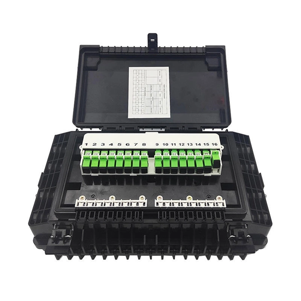
This splice case protect fiber optic cables and juction from outside plant environment damage. They are made of reinforced ABS or PC plastic, which has high strength and corrosion resistance. In addition, the splice enclosures are all hermetically sealing structure, waterproof and. Standard polycarbonate (PC) or Glassfibre reinforced (PC+GLAS) PP ABS (Acrylnitrile-butadiene -styrene) Slightly lower UV resistance compared with PC. Recommended for outdoor use if protected against weather influences GRP – GLASS FIBRE REINFORCED POLYESTER Polycarbonate and ABS enclosure materials. The fiber optic splice closure is a closed structure used for splicing, protecting and managing optical fibers. Its material selection is crucial to ensure the quality and service life of the fiber optic splice closure. These boxes are well suited as optical cable splice collection points for DAS (Distributed Antenna Systems), MTU (Multi-Tenant Unit) commercial business applications, and MDU (Multi-Dwelling Unit). It is a reentry box which is made of PC or PP material. The shells and the base are sealed with silicone gum. This product can be re-entered and used again after it is opened. Typically selected for high-density OSP splicing and branching. What is the basic structure of Fiber Optic Splice Closure? The basic structure of Fiber Optic Splice Closure includes the box body, box components, sealing ring, and lock buckle.
[PDF]
When you see “PON” on your router, it stands for Passive Optical Network. This light indicates the status of your fiber connection to the network. Passive optical networking (PON), like active optical networking, uses fiber-optic cabling to provide Ethernet connectivity from a main data source to endpoints. While there are many subtle differences, a clear distinction between active optical networking and PON topology is PON's use of a. A passive optical network (PON) is a fiber-optic telecommunications network that uses only unpowered devices to carry signals, as opposed to electronic equipment. In practice, PONs are typically used for the last mile between Internet service providers (ISP) and their customers. The purpose of an OLT is to control, convert signals and coordinate fiber optic service (FiOS) within a PON system. An ONT. Turn off the router and disconnect the power cord. Locate the optical network (PON) port on your router. Inspect the PON cable for make sure that it is correctly connected to the router. Instead of running a separate fiber strand to every home or office, a PON shares a single fiber using optical.
[PDF]

Every fiber optic patch cable has a rated attenuation and bandwidth. For example, OM1 is rated at 200 MHz·km at 850 nm and is intended for use in legacy applications. The higher OM ratings provide more speed and distance. Attenuation should remain within acceptable limits for reliable transmission. Executive Summary: Choosing the right fiber patch cable is one of the most consequential decisions in network infrastructure planning. The wrong choice — whether it's an underperforming multimode grade or an unnecessarily expensive singlemode run — can either cripple your network's reliability or. Fiber optic patch cords are key components for efficient, low-loss optical signal transmission between devices and fiber optic cabling links. One or both ends of the patch cord are equipped with standardized fiber optic connectors, and common interfaces include LC, SC, FC, ST, etc. They are manufactured and tested in compliance with TIA 604 (FOCIS), IEC 61754 and YD/T industry standards. OM1, OM2, OM3, OM4, OM5 or OS2 fiber types are available to meet the demand of. Fiber optic patch cables are ideal for supporting high speed telecommunication network fiber applications. They are lengths of optical fiber terminated with connectors on both ends. Their job is to connect two optical devices, like switches, routers, or optical transceivers that communicate.
[PDF]
Fiber Optics Market was valued at USD 8. 1 billion in 2023 and is anticipated to grow at a CAGR of over 5% between 2024 and 2032. The demand for high-speed broadband access is accelerating with end-users increasingly seeking high-quality multi-gigabit services to power their homes and. Fiber Optics Market was valued at USD 8. Cartesian received input to this study from across the industry and nation. Respondents spanned the fiber construction ecosystem from. Market Size by Fiber Type (Glass Fibers, Plastic Optical Fibers), by Cable Type (Single-mode, Multi-Mode), by Deployment (Underground, Aerial, Underwater) by End User & Forecast. 8 billion by 2029 from USD 3. 4% from 2024 to 2029. Rapid expansion of data centers, cloud services, and 5G infrastructure is driving strong adoption of fiber optic solutions. The global deployment of 5G networks by telecommunications.
[PDF]
FiberFin offers products specifically designed for the wide variety of sensor applications that POF is used in. There are three common methods for measuring external forces using plastic optical fiber. Optical fiber sensors have revolutionized the way we measure and monitor various physical and chemical parameters in different industries. These sensors utilize the properties of light to detect changes in the environment, making them highly sensitive and accurate. In this article, we will explore. Fiber Optic Sensors for Plastic Components by Application (Electronic Product, Automobile, Industrial Equipment, Others), by Types (Single-Tube, Double Tube, Multitube), by North America (United States, Canada, Mexico), by South America (Brazil, Argentina, Rest of South America), by Europe (United. While fiber optic cables can be used to connect remote sensors to electronic loggers or signal processors the same way that copper wires can, they can also be used as sensors themselves.
[PDF]