The primary problem encountered is signal loss, also known as attenuation. Attenuation can be due to absorption, scattering, or bending losses, affecting the quality and speed of data transmission. Attenuation in fiber optic cables is the reduction in signal strength during. To be able to judge whether a fiber optic cable plant is good, one does a insertion loss test with a light source and power meter and compares that to an estimate of what is a reasonable loss for that cable plant. The estimate, called a "loss budget" is calculated using typical component losses for. F iber optic networks rely on the efficient transmission of light signals to deliver high-speed data over long distances. However, various factors can cause signal degradation, leading to performance issues and reduced network reliability. Fiber optic signal loss, also known as attenuation, occurs. A significant signal loss in the optical fiber can cause unreliable transmission. How can we know the value of losses on the fiber link? Read on, this post will teach you how to calculate the losses in optical fiber and judge the fiber link performance. The uses various types of network cables, including multimode and single-mode fiber-optic cable. It can also break your connection. High attenuation makes your system not work well. You should fix it fast to get speed and stability back. > You can solve this with simple steps.
[PDF]

The OPPC cable (Fiber Optic Composite Aerial Phase Conductor) is an innovative optical cable that integrates electrical power transmission and optical fiber communication. By incorporating fiber optic units inside the phase conductor, it ensures both energy transmission and. Electrical utilities have networks used to transmit and distribute electrical power over a large geographic area. In their served areas will be power generating stations, alternative energy sources (solar, wind, geotherman, etc. ), substations for distribution and microgrids. These networks must be. wer transmission systems. The cable is used in power transmission lines, due to its excellent performance in low and medium-voltage electrical networks. This article will provide some knowledge of OPPC cable. What is OPPC. Optical Phase Conductor (OPPC) is used as an alternative telecommunications solution when there is no existing ground wire, meaning Optical Ground Wire (OPGW) is not a viable option. It combines optical fiber technology with traditional conductors, enabling real-time monitoring, improved performance, and increased reliability of.
[PDF]

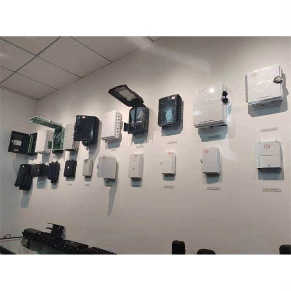
This complete guide covers everything from identifying causes of failure to advanced repair techniques, drawing on the latest industry standards and innovations. A fiber termination box is the standard instrument used in fiber optic networks to connect, secure, and protect optical fibers at the terminating point. Proper installation and maintenance of FTBs are essential to ensure the reliability and performance of the network infrastructure. Before. By understanding these key elements and following the outlined steps, you can effectively repair fiber optic cables and maintain the high-performance network necessary for today's demanding communication needs. Whether you're a network technician, IT professional, or telecom operator, you'll find practical steps, tools, and tips to restore. FTTP or fiber To The Premises applications have reinforced the importance of reliable and stable fiber optic terminations. Good quality fiber laying and termination systems help achieve minimal back reflection and low signal loss. They also feature resistance to moisture, impact, chemical exposure. A fiber optic distribution box, also known as a fiber optic terminal box or fiber optic termination box, is a device used to connect and manage fiber optic cables in a network. The distribution box provides.
[PDF]
The numerical aperture (NA) of an optical fiber is the number that defines the range of angles over which the fiber can receive, guide, and release light rays. A2=2m,300Vcable F4=pigtailw/4-pinDCmicroQD G3=pigtailw/3-pinACmicroQD Y4=pigtailw/4-pinDCpicoQD X4=custom4-pinconnector Notallvariationsavailable. Contactfactoryforavailability. Has simple set-up and configuration. The D10 Expert detects the web if it droops into the sensor's beam because the tension is too loose; the D10 then sends a signal to the controller to adjust. Product will be phased out and can be ordered until 2026-11-30. WLL80P-22T6Y1DZA71Z1Z1 Sensing range max. However, sensors based on fiber‐optics have been developed rapidly because of their excellent sensing performances and capability to function in remote and harsh environments. The usage of fiber‐optic sensors has flourished in many fields over the past 30 years due to the fiber‐optic's inherent. A colour sensor is a type of "photoelectric sensor" which emits light from a transmitter, and then detects the light reflected back from the detection object with a receiver. Detection in Narrow Locations The small sensing section and flexible Fiber Unit cable enable a Fiber Sensor to detect.
[PDF]
This section provides an overview for fiber optic sensors as well as their applications and principles. Also, please take a look at the list of 18 fiber optic sensor manufacturers and their company ranki.
[PDF]
Interferometric fiber optic current sensors (FOCS) employ circularly polarized light traversing a closed loop path around an electrical conductor's current-generated magnetic flux, which reflects off a mirror. The light experiences a reciprocal phase shift as the refractive index, and effective path length, is modulated by the presence of a magnetic field, which optically induces circular. OverviewA current sensor (FOCS) is a device designed to measure. Utilizing a single-ended optical fiber wrapped around the current conductor, FOCS exploits the (. As FOCS are resistant to effects from magnetic or electrical field interferences, they are ideal for the measurement of electrical currents and high voltages in or other environme.
[PDF]

FOCS systems can measure currents up to 700 kA. They offer a practical alternative to traditional Hall-effect sensors, using a lightweight, clamp-on design that allows installation without opening bus bars — reducing time and complexity. A fiber-optic current sensor (FOCS) is a device designed to measure direct current. Utilizing a single-ended optical fiber wrapped around the current conductor, FOCS exploits the magneto-optic effect (Faraday effect). The result is exceptional accuracy and reliability. Based on the magneto-optic effect, FOCS can measure uni- or bidirectional DC ering signal disturbance immunity available for complex industrial processes. It is unaffected by stray magnetic fields at the plant, s. The FS205 is a high precision DC high current measurement device based on the Faraday Magneto-optical Effect and the Ampere Loop Theorem. The sensing optical fiber is fixedly mounted on the high current busbar through a skeleton and forms a closed optical fiber loop. They are immune to electromagnetic interference (EMI) and do not suffer from magnetic saturation, which improves accuracy, simplifies installation, and enables reliable digital. A fiberoptic sensor that uses diverse fiber units to support various applications in virtually any environment. These are reliable and easy-to-use devices that have high power, can automatically adjust to real-time conditions, and have a straightforward display that eliminates any guesswork.
[PDF]
The Fiber Optic Sensors market was valued at USD 2,560. 00 million in 2018, reached USD 3,547. Starting at USD 2. By 2035, it is projected to reach USD 6. 3% throughout the forecast period from 2026 to 2035. I need the full data tables. As per Market Research Future analysis, the Fiber Optic Sensor Market Size was estimated at 3. 08 USD Billion by 2035, exhibiting a compound annual growth rate (CAGR) of 10. 22% during the. Fiber optic communication relies on light waves, which are difficult to intercept or tamper with, making fiber optic sensors an attractive option for industries that require secure data transmission. I need the full data tables, segment breakdown, and competitive landscape for detailed regional analysis and. Global Fiber Optic Sensors Market Research Report By Type (Intrinsic, Extrinsic), By Component (Receiver, Transmitter, Fiber Optic Cable, Optical Amplifier), By End-User (Transportation, Medical, Defense, Industrial, Oil and Gas), By Region (North America, Europe, Asia Pacific, Latin America. Global Fiber-Optic Sensors Market Size By Type of Fiber-Optic Sensors (Intrinsic Fiber-Optic Sensors, Extrinsic Fiber-Optic Sensors), By Sensing Parameter (Temperature Sensors, Pressure Sensors), By Application Sector (Aerospace and Defence, Oil & Gas), By Technology (Fibre Bragg Grating.
[PDF]

The setting value can be finely adjusted manually. Press and hold the and buttons simultaneously for three seconds. Use the to select "rSt", then press the button. Settings are summarized in "Basic" and "Advanced" categories. Providing quick solutions for every scenario. In cases where more advanced features or troubleshooting is necessary, the "Advanced". This video covers how to setup and configure the Wenglor OPT2041 Fiber Optic Sensor from AutomationDirect. **Please check our website for our most up-to-date product pricing and availability. This sensor works with both Plastic and Glass fibers. Keep in mind that the color and reflectivity of the. The KEYENCE FS-N10 Fiber Sensor is a versatile and reliable device used for detecting objects. This sensor uses a fiber optic cable to transmit and receive light, allowing for accurate and precise detection in a variety of applications. The FS-N10 series is capable of detecting objects of different. Fiber optic Sensors; How to program Keyence Fiber optics amplifier from EMI Documentation can be found here:. This is the SET push button; this is used to calibrate the sensitivity.
[PDF]
Scientists have demonstrated a new fiber-optic sensing method that detects strain and displacement by reading interference patterns directly in the electrical spectrum of a photodetected signal. They used a polymer optical fiber-based single-mode–multimode–single-mode (SMS). Electrical-domain interference in polymer optical fibers offers a simpler route to fast sensing without conventional optical-spectrum analysis. This image summarizes the newly demonstrated sensing principle. Published in IEEE Sensors Journal on April 27, 2026. Researchers have unveiled a groundbreaking fiber-optic sensing technique capable of detecting strain. This review focuses on MMI fiber sensors for nonconventional physical variables, including mechanical, electromagnetic, chemical, and optical, covering around fifteen years of work in the field. Finally, by the end of this paper, we also review some new trends of MMI-based schemes based on polymer.
[PDF]

In this guide, we'll break down the essentials, explore different wiring configurations, and provide you with practical tips to get your sensors up and running smoothly. So, grab your tools, and let's get started! Before we jump into wiring diagrams, let's quickly recap what fiber optic sensors are. working principle: Fiber optic sensors use the propagation characteristics of light to detect or measure various physical and chemical quantities. Here are some basic working principles of fiber optic sensors: Propagation of Light: An optical fiber consists of two parts: a core (the central part of. A Fiber Sensor is a type of Photoelectric Sensor that enables detection of objects in narrow locations by transmitting light from a Fiber Amplifier Unit with a Fiber Unit. Detection in Narrow Locations The small sensing section and flexible Fiber Unit cable enable a Fiber Sensor to. Click to download the ODiSI Fiber Optic Sensor Installation Guide. The following instructional videos explain how to install, configure, and calibrate the FiberPatrol FP400 fiber optic fence-mounted intrusion detection sensor. Copyright © 2026 Senstar Corporation. Legal | Accessibility. Surprisingly Stable Detection with Your Finger tip. Exceptionally easy operation and stabilizing technology reduce maintenance cost. If you Login / Signup, you can download the PDF of the Manual. Please note some product models not sold in Singapore may be included in the following manual (s) for.
[PDF]
A fiber-optic sensor is a that uses either as the sensing element ("intrinsic sensors"), or as a means of relaying signals from a remote sensor to the electronics that process the signals ("extrinsic sensors"). Fibers have many uses in. Depending on the application, fiber may be used because of its small size, or because no is needed at the remote location, or because many sensors can be along the length of a fiber by using light wavelength shift for.
[PDF]
An optical fiber is a cylindrical ( waveguide) that transmits light along its axis through the process of total internal reflection. The fiber consists of a core surrounded by a layer, both of which are made of materials. To confine the optical signal in the core, the of the core must be greater than that of the cladding. The boundary between the core and cladding m.
[PDF]