An optical modulator is a device which is used to a. The beam may be carried over free space, or propagated through an (). Depending on the parameter of a light beam which is manipulated, modulators may be categorized into amplitude modulators, phase modulators, polarization modulators, etc. The easiest way to obtain modulation of intensity of a light beam is to modulate the current driving the light source, e.g. a. This sort of modulation is c.
[PDF]

This paper will review the development of fiber-optic high-temperature sensors over the last 30 years, presenting their design and fabrication methods according to sensing type and typical temperature measurement performance. The full paper consists of eight sections. Fiber-optic high-temperature sensors are gradually replacing traditional electronic sensors due to their small size, resistance to electromagnetic interference, remote detection, multiplexing, and distributed measurement advantages. This paper reviews the sensing principle, structural design, and. Luna's Optical Backscatter Reflectometer (OBR) products are based on OFDR and provide a level of detail and precision not available with the prevailing fiber optic diagnostic tool - the optical time domain reflectometer (OTDR). OBR systems map out loss along a single-mode fiber (SMF) or multi-mode. breadth and most comprehensive solutions for optical communications test products to be found in one place. Corning's High Temperature Fibers are designed for applications requiring improved fatigue resistance, high usable strength, and excellent resistance to higher temperatures and hydrogen permeation. Thus, wireless communication -situ processing of data would combined with in significantly improve the ability to include sensors into high temperature systems and thus lead toward more intelligent engine systems. NASA Glenn Research Center (GRC) is presently lea, communication systems,ding the.
[PDF]

Managing optical attenuation helps keep your signal safe. Clean your optical connectors so you do not lose. Optical Signal Attenuation is the single greatest factor limiting the distance and performance of your network. Understanding it is crucial for anyone involved in data centers, telecommunications, or enterprise networking. This guide will demystify signal loss, explore its causes, and show you how. In high-speed environments, where the optical link budget is measured in fractions of a decibel, diagnosing and eliminating unexpected loss is the network engineer's most critical task. This field guide provides a systematic, step-by-step approach to troubleshooting and resolving the most common. Signal loss in Fiber Optic networks can make data slow. It can also break your connection. You should fix it fast to get speed and stability back. > You can solve this with simple steps. Signal Degradation (Loss of Light) When the signal quality degrades, it could be a sign of attenuation or excessive loss in the system. The signal might become weaker, resulting in slower speeds or dropped connections. -. Fiber optic networks are celebrated for their speed and reliability, but even the best systems can encounter problems. When issues like signal loss, slow speeds, or intermittent connectivity arise, systematic troubleshooting is key. Things like impurities in the fiber core and reflections at the core-cladding edge cause this drop.
[PDF]

Telescopic mast system with advanced vibration-dampening technology to minimize jitter and ensure stable communication and data transmission, even in the most demanding terrain and vehicle movements. Fireco designs and manufactures the most comprehensive line of standard and custom telescopic masts using high quality materials with industry leading engineering and quality testing practices to provide our customers with the world's best mobile masts. Will-Burt's telescopic masts and tower systems provide intelligent. Telescopic mast systems play a critical role in modern field operations—enabling elevation of cameras, antennas, lights, sensors, and communication gear in demanding environments. Whether for surveillance, broadcasting, defense, or emergency response, choosing the right mast system ensures reliable. Floatograph, along with its utility industry partner, Eversource Energy, developed the Rapid Pole® – Temporary Power Pole system to reduce customer downtime, allowing crews to re-energize a circuit in as little as 20 minutes. Floatograph's masts come in height options from 10 to 100 feet, and are. Advanced telescopic mast solutions designed for versatility in the field, providing crucial support for on-the-move (OTM) missions. Erecting the Telescoping Mast is made by simply connecting guys and brackets to the attached unique heavy duty rolled edge guy rings and clamps, extend the sections, insert the locking cotter pins, rotating the tubes to.
[PDF]

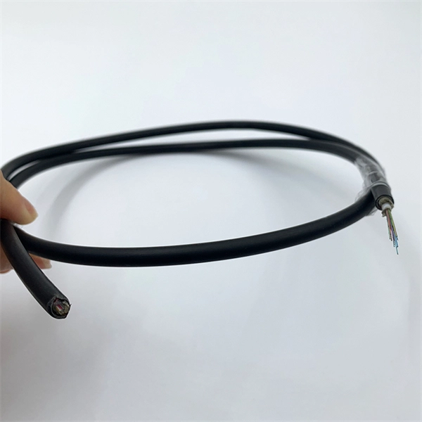
The zero-buoyancy rov cable was born as a power connection and control of underwater robot equipment, as well as signal transmission and feedback link cable applications. The zero-buoyancy cable has been tested by the market and practice due to its excellent. The global underwater zero buoyancy cable market is experiencing robust growth, driven by the expanding offshore energy sector, increasing demand for subsea infrastructure development, and advancements in underwater communication technologies. Linden Photonics is renowned for its innovative fiber-optic solutions, specifically designed for Remote Operated Vehicles (ROVs). These ROV tethers are crucial in underwater applications, offering high performance, durability, and reliability in challenging environments. For use with ROV's (Remote.. Customizable neutral buoyancy fiber optic power cable for ROVs and underwater drones. High‑performance hybrid design combining power and data in one composite cable. Engineered for seawater resistance, flexibility and subsea reliability. Suitable for inspection systems, subsea cameras and. At Invocean, we understand the increasing demands and the critical nature of Remotely Operated Vehicles (ROVs) in various industries such as underwater construction, surveillance, salvage, and scientific research. To support these high-performance tasks, ROVs and Micro-ROV's require reliable.
[PDF]

Solution: To solve this problem, you can follow these steps: Check if the fiber and optical modules are compatible. A switch must use optical or copper modules that have been certified for use on Huawei switches. Huawei is not liable for any problem caused by the use of non-certified optical or copper. This article summarizes several solutions for using optical modules with switches and common problems encountered during usage, along with specific solutions. Huawei S5720-32P-EI-AC Switch II. During use, reading optical module information helps understand its real-time operating status, enabling faster troubleshooting of link abnormalities. The following uses the. ers, only the short transmission distance is supported. Whether optical attenuators need to be deployed at the receive end o. A leaf-spine refresh can fail in subtle ways: a port locks in an unexpected speed, optics negotiate but traffic stays dark, or DOM readings mismatch. This case study helps network engineers and field technicians validate a Huawei CloudEngine transceiver against switch requirements before rollout.
[PDF]
A photonic integrated circuit (PIC) or integrated optical circuit is a microchip containing two or more photonic components that form a functioning circuit. This technology detects, generates, transports, and processes light. Photonic integrated circuits use photons (or particles of light) as. architecture and performance of several generations of InP-based PICs. Increased complexity in chip functionality has resulted in a need for increased fabricati n complexity from III-V epitaxy, through wafer fab, die fab, and test. Through continuous learning and improvement, Infinera has. Photonic integrated circuits (PICs) use light (photons) to transmit information, whereas traditional integrated circuits use electricity (electrons), enabling faster signal propagation. Whereas an electronic integrated circuit.
[PDF]
Find Ecuadorian optical fiber cable joint closure importers on ExportHub. Our team of fiber optic specialists is always available to provide expert advice and tailored solutions, ensuring you get the best connectivity for your needs. LatamFiberHome designs and produces a wide range of optical cables for indoor, outdoor and all kinds of cable structures under customer requirements. At the same time it has a complete set of test equipment to ensure that the cable produced meets international standards and customer requirements. According to the structure can be classified into the dome (vertical) and horizontal (half) two kinds of cable splice closure. Nortra Cables offers custom cable and wire harness design assistance, prototyping and manufacturing services for medical, computer, communications, industrial, and electromechanical applications. Some types of manufactured assemblies include: Loom Harnesses, Box Builds, Prototyping, Coaxial Cable. OPTICALFIBRE CABLES OF EXTENSION CORDS IN 30 PALLETS NET WEIGHT 14843, 50 KG/ 32723, 68 LBS GROSS WEIGHT 15318, 50 KG/ 33770, 85 LBS. The companies listed above have not approved or sponsored Panjiva's provision of any of the information in these.
[PDF]
The Open Systems Interconnection (OSI) model is a developed by the (ISO) that "provides a common basis for the coordination of standards development for the purpose of systems interconnection." In the OSI reference model, the components of a communication system are disting.
[PDF]

GYTA is an outdoor stranded loose tube fiber optic cable with aluminum tape armor (indicated by the “A” in GYTA). It is designed for aerial and duct installations but is not recommended for direct burial. It provides an excellent balance of moisture protection and mechanical flexibility, making it the preferred choice for duct and aerial backbone networks. Perfect for long-distance communication. We manufacture high quality products according to European and US standards. The aluminum. Outdoor Duct Optical Cables are strands of specially designed fiber optic cable that are ideally suitable for deployment in underground conduits or ducts. This type of cable guarantees total security for optical fibers while providing long-distance, high-speed data transmission. We supply GYTA fiber optic cable from 2 fiber cores to 288 fiber cores. Both single mode type and multimode types are available. precise control for fiber excess. GYTA fiber optic cable is an outdoor loose tube cable that uses aluminum tape armor for additional mechanical protection. This cable design is commonly installed inside underground ducts or conduits where fiber cables require protection from external pressure and environmental conditions. It is known for its high tensile strength, high flexibility, and excellent transmission performance. In this article, we will discuss the characteristics of the GYTA optical cable.
[PDF]

The answer is yes, and it's a practice widely used in the industry to distribute signals to multiple destinations without degrading the signal quality significantly. This article delves into the methods, benefits, challenges, and practical applications of splitting fiber lines. In principle, an optical cable can be split, but it's not as simple as just cutting the cable and attaching multiple devices. There are two primary methods of splitting an optical cable: Passive splitting involves using a specialized device called an optical splitter. This device takes the incoming. A fiber optic splitter is a passive optical component that divides a single incoming optical signal into two or more outgoing signals, or combines multiple incoming signals into one. What is Fiber Line. An optical splitter, also known as a beam splitter, fiber splitter, or fiber optic splitter, serves as a vital passive component in optical communication systems. Its primary function is to split the optical signal of one input optical fiber into multiple optical signals and transmit them to. An MPO breakout cable is a fiber optic cable designed to split a single multi-fiber connection into multiple separate connections. Fiber optic splitters have applications such as Fiber to the Home (FTTH) and Passive.
[PDF]
Optical cable junction boxes play a crucial role in connecting and protecting optical fibers, directly influencing the quality and lifespan of optical cable routes. Optical cable splice boxes protect the splicing parts of optical fibers from various hazards, such as water seepage due to adverse. Optical cable junction boxes play a crucial role in managing and organizing fiber optic networks. It serves as a termination point for fiber optic cables, providing protection and distribution of the optical fibers while ensuring efficient signal transmission. Utilizing an optical junction box can significantly enhance your. Optical cable splice box is a popular name, its scientific name is optical cable splicing box, also known as optical cable splicing package, optical cable splicing package and gun barrel. These boxes are designed to house and protect fiber optic splices and terminations, ensuring that the delicate fibers are safeguarded from.
[PDF]
The SFP-1040-WB is a BiDirectional single fiber strand 10G SFP+ optical module using Tx:1330nm and Rx:1270nm wavelengths. The transceiver supports all 10G rated speeds for Ethernet, SONET, SDH or Fibre Channel networks. SFP-1040-WB must be paired with the SFP-1040-WA model to have an operational. The SFP-1040-Wx series single mode transceiver is small form factor pluggable module for duplex optical data communications such as 10GBASE-ER/EW defined by IEEE 802. It has the SFP+ 20-pin connector to allow hot plug capability. All modules satisfy class I laser safety requirements. Digital diagnostics functions are available via a 2-wire serial. The SFP-1040-Dxx is a DWDM 10G SFP+ optical module. It is available for all 45 DWDM 100GHz ITU grid wavelength channels. The transmitter section uses a 1550nm EML, which is class 1 laser compli Rate Select 0, optionally controls SFP+ module recei e Select 1, optionally controls SFP+ module.
[PDF]


