
It plugs into network equipment (like switches, routers, or servers) and its primary function is to convert electrical signals from the device into light signals for transmission over fiber optic cables, and then convert received light signals back into electrical signals. People can also refer to an optical transceiver as a fibre optic transceiver or optical module. A transceiver is a mix of the words 'transmitter' and 'receiver. ' An optical transceiver includes an optical. This section explains the core IP and optical components used in traditional hierarchical networks. It helps readers understand the router, transponder, ROADM, amplifier, and management elements that form the baseline network architecture. In fiber optics, this data is sent in the form of pulses of light over an optical fiber, at very high speeds and across long distances. Essentially, these devices. Why choose Nokia for your optical network? The Nokia industry-leading optical network portfolio leverages highly vertically integrated coherent optical engines and includes the latest generation of open and flexible optical line systems, intelligent coherent pluggables, ultra power-efficient. This page provides an introduction to optical wireless networks. It compares short-range (directed and diffused) and long-range optical wireless technologies, highlighting their differences. The broadband wireless.
[PDF]

An optical network is a communication system that leverages light to convey information across distances, encoding data into rapid flashes of light instead of relying on electrical voltage changes. At the heart of this ecosystem lies the Optical Transport Network (OTN) — a framework defined by the ITU-T (notably G. 709) that has become the foundation for modern optical communications. This method allows engineers to manage the exponential growth in global data traffic generated by. A passive optical network (PON) is a system commonly used by telecommunications network providers that brings fiber optic cabling and signals all or most of the way to the end user. Depending on where the PON terminates, the system can be described as fiber to the curb, fiber to the building or. An Optical Transport Network (OTN) is a transmission network based on wavelength division multiplexing (WDM) technology. It is a specific type of transmission network that transmits data and manages it using optical signals. OTN is built on a series of protocols, including G. It is designed to provide a high-speed, scalable, and reliable infrastructure for the transmission of data between different network nodes. While there are many subtle differences, a clear distinction between active optical networking and PON topology is PON's use of a.
[PDF]

Connect the red wire to the copper wire with the red color bar of the optical/electrical composite cable, and connect the black wire to the other copper wire of the optical/electrical composite cable. Then press and secure the crimp tube. Ensure that no copper. The composite fiber optic cable is a type of cable that combines both fiber optic and copper conductors within a single cable sheath. This hybrid construction allows for the simultaneous transmission of data using fiber optics and electrical power or additional data using copper conductors. How to Use the Composite Fiber Optic Cable? To begin, you need to gather all the accessories and equipment required: 1. Waterproof Industrial-Grade Fiber PoE Media Converter Compatible with the IEEE802. Cut the cable along the center and pull one copper cable on the left and right sides to the position shown in the figure to expose the optical fiber. Whether you're a seasoned technician or a beginner, this guide has something for everyone. more In this video, we'll walk you. In a previous blog, we covered what to do when you need to connect a device that is located beyond the 100-meter distance requirement and described four ways to address the problem—a new TR, the use of an extender device, extended-reach copper cable and fiber. This article will guide you through the necessary tools, materials, and methods on how to connect fiber optic cables effectively.
[PDF]

Scattering accounts for the greatest amount of attenuation in a fiber cable, between 95 and 97 percent. Light traveling through the fiber interacts with the densities as shown in the light and is then partially scattered in all directions. Fiber optic cables have many advantages, but one of the downsides just like with copper cable, is that it can experience what is called attenuation. Attenuation refers to the loss of light as it travels down the fiber. This can be due to a variety of factors: scattering and absorption, intrinsic. This attenuation is inevitable, so the smaller the attenuation value, the longer the transmission distance of the same optical power. The better the quality of this fiber patch cable. It indicates the amount of signal reflected back. At TREND Networks, we are frequently asked how much loss is allowed when conducting testing on fiber optic cabling. Unfortunately, it is not a simple answer and depends on several factors. So how do you determine acceptable loss? When testing fiber optic cabling, determining acceptable loss is. Understanding fiber loss is vital in maintaining a reliable, efficient network. Understanding it is crucial for anyone involved in data centers, telecommunications, or enterprise networking. Here are the details and instructions about each field and how they contribute to the calculation: 1. Attenuation Coefficient (dB/km): This value represents the inherent signal loss per kilometer of.
[PDF]

How to Connect Fiber Splitter & Configure ONU with OLT | Onu connected Vsol olt through splitter . more. How to Connect OLT and ONU Devices? To configure the ONU easily, it must first be connected to the OLT. more. The OLT communicates with the optical network unit (ONU) or optical network terminal (ONT) at the user end, coordinating the distribution of data and ensuring that each connected user receives the appropriate information. Equipment Components Generally speaking, OLT equipment includes a rack. FTTH (Fiber To The Home) is a technology that provides high-quality internet access directly to consumers' homes over an optical fiber infrastructure. This provides users with a dependable and high-speed network service and little to no wait times. This network is suitable for building. FTTH (Fiber-to-the-Home): This is a broadband network architecture where optical fiber runs directly to the customer's home, providing extremely high-speed internet, video, and voice services. OLT (Optical Line Terminal): The OLT is located at the service provider's central office or point of.
[PDF]
Optical Fiber Cable & Accessories Price in Nepal, Kathmandu. Buy with best and reasonable price @ ITShop Nepal. Nepal - Shop for Best Online at Daraz. np Wide Variety of fiber optical cables. Great Prices, Even Better Service. Copyright © 2026 Janaki Cable Industry. Powered by one tech® View the latest retail rates for Janaki Cable products effective from Apr 20 2026. Includes per-meter prices for Copper/Aluminum Armoured Power Cables, Multistrand Flexible Wires, and FRLS Cables. The Nepalese optical fiber cables market fell slightly to $X in 2025, dropping by X% against the previous year. This figure reflects the total revenues of producers and importers (excluding logistics costs, retail marketing costs, and retailers' margins, which will be included in the final consumer. SÜRGÜLÜ PATCHPANEL SC UPC DUBLEX 24XADAPTÖR 48XPIGTAIL RAL7035 1u 19” MEK. SÜRGÜLÜ PATCHPANEL SC UPC DUBLEX 12XADAPTÖR 24XPIGTAIL RAL7035 Buy Fiber Optic Infrastractures and Accessories in Nepal at best price from platforms Hub. is a leading Internet & TV service provider in Nepal. Since 24 years, Vianet Communication has always remained at the forefront, providing reliable and affordable Fiber Broadband Internet Services.
[PDF]

We offer a wide range of OEM-compatible optical transceivers & cables, ensuring reliable, high-speed connectivity. Skylane Optics offers the full range of transceivers with an unique set of services, such as testing, coding, customization, effective support & technical expertise. The transceiver-cable consists of two transceivers directly attached to one piece of cable (either copper or fiber). There can be. Approved Technology specialises in compatible network transceivers, DACs, AOCs and networking equipment. Download our latest catalogue of transceivers, passives, jumpers, meters and more. Select components and request pricing for your aplication. Get valuable industry and product updates and. Our Optical Receivers and switches are produced to ensure maximum quality and efficiency for the FTTx network. Our optical receivers have a high and constant RF output level within the whole optical input power range by an integrated automatic gain control. How does our search work? With MEET OPTICS search you get direct access to our database of thousands of optical components from providers worldwide. Prices and product specifications directly listed from optical component. XTEL is rapidly becoming an authority in all aspects of MSA (multi-source agreement) standards compliant copper and fibre optic transceivers, including coding/programmeing, testing and distribution to anywhere in the world. Why choose our.
[PDF]

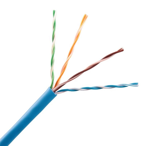
For most setups, cables with 12, 24, or 48 cores are common choices, ensuring compatibility with modern equipment and ease of management. Fiber cores are the heart of fiber optic cables, transmitting light signals that carry data. Made from either high-quality glass or plastic, the core plays a critical role in determining the cable's performance. The total number of cores for a 1pc fiber patch cable is calculated as the number of. In fiber optic cables, data is transmitted as pulses of light that travel along a thin strand of glass or plastic fiber. The light is typically. The number of optical cores in an optical fiber is the total number of equipment interfaces multiplied by 2, plus 10% to 20% of the spare quantity, and if the communication mode of the equipment has serial communication and equipment multiplexing, you can reduce the number of cores. The following ZR Cable introduces some methods to determine the number of fiber cores. First of all, clearly know the number of wiring points in this layer, calculate the number of switches, and whether the connections. A fiber-optic cable, also known as an optical-fiber cable, is an assembly similar to an electrical cable but containing one or more optical fibers that are used to carry light. ” However, when light enters the core it needs to remain within it, and one layer that ensures that is called.
[PDF]
Genuine Modules mentions that the cost of fiber optics per kilometer can range from $10,000 to $50,000, depending on various factors such as the type of fiber, installation method, terrain, and region. Fiber-optic cable materials typically cost $1 to $6 per linear foot, depending on fiber count and cable type. Commercial building installations with 100-200 network drops generally range from $15,000 to $30,000. Single-mode fiber costs less per foot than multimode fiber, but it requires more. The price of fiber optic cabling depends on cable type, length, installation method, and surrounding materials. Typical costs hinge on fiber count, indoor versus outdoor use, and whether trenching, splicing, or termination is required. This guide provides practical ranges in USD and practical price. Discover 6 core fiber optic cable 1km price with GYXTW armored outdoor design, G652D fiber, CE/ROHS, ideal for 5G FTTH networks. Knowing how much fiber optic cable costs, which factors can impact cost, and key cost considerations can help you avoid unnecessary expense and get the most out of your budget. 50 per meter, depending on several variables. Here's a general pricing reference: These are indicative prices based on standard configurations. Custom-built cables or niche specifications can lead to higher prices. 30Single-mode Outdoor Cable$0. 50Multimode (OM1/OM2/OM3)$0.
[PDF]
The Telecoms crash, also known as the Telecommunications Bubble was a that occurred in 2001, after the bursting of the. The telecommunications industry had experienced significant growth and investment during the 1990s, fueled by the expansion of the internet and the introduction of wireless technology. Companies such as,, and had achieved enormous market valuations base.
[PDF]

Passive receiver that captures an optical signal on a single fiber (1310/1490/1550nm), and demultiplexes it (WDM). The TV signal (1550nm) is converted to an RF output (54-2400MHz), while the 1310/1490nm wavelengths are destined to data signals (GPON) to distribute them through. Facilitates rapid deployment and hassle-free replacement. Contributes to wide coverage and supports multiple optical nodes, facilitating network upgrade and expansion effortlessly. Maintains stable output with minimal gain fluctuation (±0. 5dB) and low noise signature (≤5. Supports. REF. This FTTH WDM Passive Optical Receiver is engineered for high-performance fiber-to-the-home networks. It features a passive design that operates without an external power supply, simplifying installation and reducing maintenance. With integrated WDM technology, it efficiently handles 1310nm/1490nm. Passive FTTH Optical receiver, cost-effective, no need power. ■ High quality plastic case; ■ Digital signal input -10dBm, analog signal input -7dBm; ■ Without power supply and consumption; ■ SC/APC or FC/APC; ■ Output level> 64dBuV (Pin=0dB).
[PDF]

Optical Transmitter: Converts electrical signals into optical signals for transmission. Optical modules are devices used to connect network devices, transmit and receive data between network devices, and can be used to convert optical and electrical signals. The optical module is a very important component in an optical communication system. This article will introduce you to the. d launches the optical signals into an optical fiber. A fiber optic transmitter consists of an interface c rcuit, a source drive to make it compatible with the source drive circuit. The source drive circuit intensity modulates the opt cal source by varying the current through the source. But what exactly is happening inside this powerful little component?In this article, we'll pull back the curtain and explore the inner. Optical transmitters are a crucial component in modern telecommunications, enabling the transmission of data as light signals through optical fibers. In this comprehensive guide, we will explore the definition, importance, and evolution of optical transmitters, as well as their types, applications. Role: Convert optical signals back into electrical signals and reconstruct the transmitted information., PIN diode or avalanche photodiode). Demodulation circuitry to extract the transmitted data. These requirements define digital transceivers as well as analog receivers and transmitters.
[PDF]

When it comes to testing fiber optic cables, a Visual Fault Locator (VFL) is an essential tool in your toolkit. A VFL is used to detect faults, breaks, or bends in fiber optic cables by emitting a bright red light that is visible even through the fiber's jacket. Let's dive into everything you need to know about mastering VFLs. In the. Finding a break in a fiber optic cable can be challenging but is essential for maintaining a stable network. Common Indicators of a Cable Break Signal. Here Kingfisher's experienced engineers share their experience in best practices and procedures for fiber optic testing related mostly to installation and maintenance. We hope that by sharing our knowledge, we will help grow our industry. Please enjoy & pass on these notes. The following are key methods and techniques used for optical fiber cable line failure positioning: Visual Inspection: Perform a visual inspection of the. Locating faults in fiber optic cables requires specialized tools and techniques. Look for dirt, scratches, or damage on the connectors. Clean. To ensure the quality and continuity of fiber optic services, it is essential to identify and locate fiber optic cable faults as quickly and accurately as possible. In this article, you will learn about some of the common methods and tools for fiber optic testing and troubleshooting.
[PDF]
