
A simple 1-core FTTH drop cable costs around $0. 13 per foot, while a 288-count optical fiber cable for building backbones can reach $6 per foot or more. In this article, we'll take a closer look at the main parameters determining the price of a fiber patch cord, provide up-to-date pricing ranges, and assist you in becoming a smarter buyer—regardless of whether you are making a purchasing decision for a project, replenishing inventory, or placing an. Check each product page for other buying options. Need help?. Fiber-optic cable materials typically cost $1 to $6 per linear foot, depending on fiber count and cable type. Commercial building installations with 100-200 network drops generally range from $15,000 to $30,000. Single-mode fiber costs less per foot than multimode fiber, but it requires more. Knowing how much fiber optic cable costs, which factors can impact cost, and key cost considerations can help you avoid unnecessary expense and get the most out of your budget. First. Get low-loss fiber patch cables & cords with various connector options that support fiber optic cabling up to 400G. Customized cables available. Main cost drivers include cable grade (indoor vs outdoor, armoured), distance, and labor for trenching, splicing, and termination. This guide presents ranges in USD and practical price estimates to help.
[PDF]

A 630A MCCB means the breaker is rated to handle up to 630 amperes of continuous current without tripping under normal conditions. This type of MCCB is commonly used in industrial power distribution panels, commercial buildings, and large electrical systems where higher current. A Molded Case Circuit Breaker (MCCB) is a protective device designed to automatically disconnect electrical circuits during overloads or short circuits. This type of. This ComPacT NSX630N is a complete 3P 3d fixed circuit breaker designed to optimize space and breaking capacity. It is an optimal choice for all standard and specific applications. The breaking capacity (Icu) is 50kA rms at 415VAC 50/60Hz. This product. Fuji Molded Case Circuit Breakers are more compact (especially 100A, 125A, 250A frames) than any breakers on the market, so they take up less space in control panels. U denotes non-interchangeable trip unit. With a 630A frame rating and adjustable settings from 400A to 630A, it offers flexible protection for high-power applications. Ir = 300 - 630A; Icu = Ics = 65kA at AC 440V How to request a quotation How can I request a quotation for more than one product? (Watchlist). GENLITEC POWER® GTS630 630A Automatic Transfer Switch (ATS) Panel is designed for seamless and automatic power switching between the main utility supply and backup generators. Engineered for high-power applications, this ATS ensures uninterrupted power supply, reducing downtime and enhancing.
[PDF]

Cable tray pricing depends on materials, coatings, size, supplier margins, and order quantity —plus hidden costs like shipping and installation. This guide breaks down everything buyers need to know, from price trends to cost-saving tips. Understanding the cable tray installation cost per meter is essential for effective budget planning. Costs vary based on tray material (steel, aluminum, or fiberglass), size, design (ladder or solid bottom), and installation complexity. The average cable tray price per meter ranges from $2 to. Ask ten buyers about cable tray cost, and most of them will point to the rate per meter. That number matters, but it's rarely the one that decides whether a project stays within budget. The real cost shows up later, during installation, during upgrades, and during the first few years of operation. The selection of the method of carrying wires is based on two points: the cost of the components and the cost of work. Although metal pipes (conduit) may appear cheap initially, they tend to be the most costly option when the job is finally complete, since they consume a lot of time to install. Cable tray pricing represents a crucial consideration in modern electrical infrastructure projects, encompassing various factors that influence the overall cost-effectiveness of cable management systems. The price structure typically reflects the material composition, whether aluminum, steel, or.
[PDF]

Learn how to splice 4-fiber optic cables using ODF in this complete step-by-step tutorial. Whether you are a beginner or a professional in fiber optic networking, this guide will help you splice fiber cables accurately, manage connections with ODF panels, and ensure. This complete guide explores everything you need to know about ODFs — from their structure, types, and key components, to installation best practices and modern design trends. Whether you're building a central office, data center, or FTTx distribution network, understanding the right ODF. How to Splice 4-Fiber Optic Cable with ODF | Step-by-Step Fiber Optic Splicing Tutorial. This guide demystifies ODF, exploring their design, core functions, types, and how they. An Optical Distribution Frame (ODF) is the central hub for fiber splicing, termination, patching, and cable protection in modern optical networks. It's where incoming and outgoing cables meet. It does four key things: Think of it as the central hub for your fiber network. Without it, cables get tangled. This article explores the types, components, applications, installation, and maintenance best practices, providing a.
[PDF]

As light in fibers often does not have a well defined polarization state, it is important that a fiber-optic attenuator exhibits only a minimum amount of polarization dependence. Generally, the obtained insertion loss has some dependence on the optical wavelength. Some attenuators have a relatively strong wavelength dependence and are made for working in narrow wavelength regions, e.g. with a bandwidth of only 20 nm around a center wavelength of 1550 nm. Others are optimized for a weaker wavelength dependence, making them u. For single-mode devices, the insertion loss can not depend on the direction of propagation, as long as no non-reciprocal parts are used, as e.g. in a Faraday isolator. For multimode devices, however, some loss difference is possible in conjunction with a mode dependence. For many applications, it will not be a problem if the obtained insertion loss slightly deviates from the specification (e.g. by 1 dB), or if it slightly changes over time. Example cases, however, one may require a higher precision. Most fiber-optic attenuators exhibit a relatively high return loss (at least several dozens of decibels), i.e., there is not much light which is reflected back into the input fiber. For some sensitive applications, e.g. when using an attenuator before or after a high-gain fiber amplifier, one may have two use attenuators with particularly high retu.
[PDF]

Start with the simplest, fastest checks (visual inspection, cleaning, cable routing) and only move to instrumentation (power meter, VFL, OTDR) when those steps don't clear the fault. This saves time and prevents needless part swaps. HOLIGHT Fiber Optic provides factory-direct, high-performance cables, adapters, and cleaning tools for telecom, FTTH, and industrial applications. What are the most common signs of fiber cable damage? Visible cracks, flattened jackets, sharp bends, dirty connectors, and corroded ferrules are. Fiber optic cables are the backbone of modern high-speed internet, television, and communication systems. Designed to transmit data using light pulses, these cables offer exceptional speed, bandwidth, and reliability. While these cables are engineered for durability (with some rated to last 25+ years), they are not invulnerable. Accidental cuts, breaks, or other damage can disrupt your network and cause costly downtime. With the right tools and techniques, you can efficiently repair damaged fiber cables and restore. Fiber optics is a technology that utilizes thin strands of glass or plastic, called optical fibers, to transmit data in the form of light pulses. This technology has revolutionized the field of telecommunications, offering significantly higher bandwidth and faster signal transmission compared to.
[PDF]

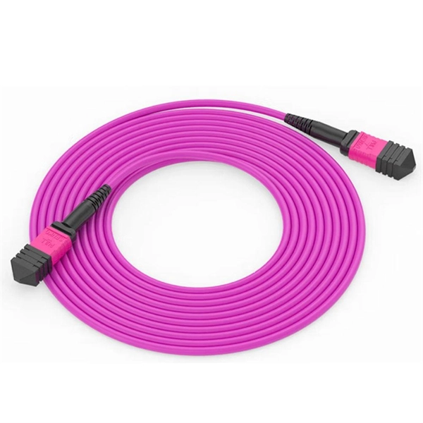
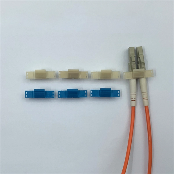
Explore 39 top manufacturers and suppliers of Fiber Optic Patch Cords in our comprehensive photonics buyers' guide. Manufacturer of fiber optics and related instrumentation, components, and assemblies for spectroscopic and laser delivery applications. Fiberopticpatchcords are also offered. Packaging, prototyping, engineering drawing, labelling, and kitting are offered as secondary services. Serves electronics. In the United States, there are many professional network patch cord manufacturers that can manufacture and supply high-quality Category 5, Category 6, and Category 6A RJ45 patch cables. But it's a bit difficult to find the best one with the most competitive price. To help you find the best. This section provides an overview for fiber patch cable as well as their applications and principles. CBO GmbH. fiber optic patch cord manufacturer should be selected by connector type, single mode or multimode fiber, polish type, cable diameter, jacket material, length, insertion loss requirement, labeling, packaging, and quantity. Products include fiber optic assemblies for. This report studies the Optical Fiber Patch Cord market, also known as fiber optic patch cable or fiber jumper, it is an Optical Fiber Patch Cord is a fiber optic cable capped at either end with connectors that allow it to be rapidly and conveniently connected to CATV, an optical switch or other.
[PDF]
These aggregation switches typically operate at Layer 2 or Layer 3 of the OSI model, depending on the network topology and configuration requirements. The three layers of a traditional three-layer network design are the core layer, aggregation layer, and access layer. As the physical part of the aggregation layer, aggregation switches typically play a. An aggregation switch consolidates data traffic from multiple network access switches into a single high-bandwidth link directed toward a core network or data center. It is essential for larger networks requiring efficient data flow. They function as gateways to collect routing information in a point of delivery. Most medium-to-large networks follow a three-tier hierarchy: access, aggregation (sometimes called distribution), and core. Each tier has a distinct job. Access switches are the ones closest to end users and devices. They sit in wiring closets or on top of server racks, providing ports for.
[PDF]

This article provides a comprehensive guide on how to capture network packets on a switched network using Wireshark, covering key concepts such as port mirroring, network tapping, and other methods to ensure you can monitor traffic effectively on a switched network. Packet capture is supported on the Cisco Catalyst 9300 Series Switches. The following sections provide information about the prerequisites for configuring packet capture. Before starting a Wireshark capture process, ensure that CPU. Embedded Packet Capture (EPC) is an embedded system management tool used for tracking and troubleshooting network packets. This tool helps network administrators capture packets entering and leaving Cisco devices. EPC can be used with Access Control Lists (ACLs) to filter specific packets based on. Packet capture and packet analysis are made possible by the multi-step packet capture protocol (PCAP), which makes use of many tools. Packet sniffers are tools used to do packet capture; they are the first step in the process. They are. Of course switches work on an entirely different principle and do not replicate unicast packets out of every port on the switch, but keep them isolated unless it's a broadcast or multicast. In traditional hub-based. This enables us to easily take captures directly from the switch and export them for analysis. The process is very straightforward and only takes a couple of minutes to set it up. The packets are then stored.
[PDF]
This video shows real on-site footage of electrical installation, demonstrating safe and standardized wiring methods used by professionals. more Learn how to wire a distribution box step by step!. A distribution box is the heart of any electrical system. It takes the incoming power and safely distributes it to different circuits throughout your building. Whether in a home or an industrial facility, this box keeps your electrical setup organized, functional, and efficient. However, the key to. In modern electrical systems, cable distribution boxes (also known as electrical distribution boxes or distribution boxes) play a crucial role as the key hub for managing, distributing, and protecting circuits. It serves as a central hub for distributing electricity throughout a building, ensuring that power is delivered safely and efficiently to all the required locations. Box installation: Make sure that Distribution box has been correctly installed and fixed. Material preparation: Prepare the required circuit breakers, wires, wiring ties and other materials, and ensure that they meet the design drawings and installation requirements. Location determination:.
[PDF]
It is relatively affordable, especially when considering its durability and long lifespan. Additionally, it requires minimal maintenance, reducing ongoing costs. It is generally easy to install and can be quickly integrated into different systems or structures. Cable Tray is often a cost-effective solution compared to other materials. However, since this design is open, it. Cable tray pricing depends on materials, coatings, size, supplier margins, and order quantity —plus hidden costs like shipping and installation. This guide breaks down everything buyers need to know, from price trends to cost-saving tips. Additionally, these solutions help ensure compliance with fire safety codes and regulations, fostering a safer environment. Ensure your infrastructure's safety with NewReach Fire Rated. Lightweight: GRP cable trays are significantly lighter than metal cable trays. Electrical Insulation: GRP cable trays provide excellent electrical insulation. The landscape is shaped by regional manufacturing dominance and evolving buyer preferences. The market is growing steadily, driven.
[PDF]

In this guide, we'll walk you through exactly how to splice fiber without a fusion splicer, covering the tools you need, the step-by-step process, performance specs, and common mistakes to avoid. By the end, you'll be equipped to make clean, low-loss connections in any. In this guide, we cover the basics of fiber optic splicing, how to perform splicing using two different methods, and finally some best practices to perform good fiber splicing. What is Fiber Optic Splicing and Why is it Needed? – #1. Use and Maintain Your. Optical fiber fast connectors, also known as cold connectors, are becoming increasingly popular due to their ease of use and quick installation. Unlike traditional fiber connectors that require epoxy and polishing, fast connectors use a mechanical splice to join the fibers. What is a. Three methods for connecting two fiber optic cables: fusion splicing, mechanical coupler, and splicing. Whether repairing a broken cable or extending a fiber run, fiber optic splicing ensures light signals travel. Fiber optic splicing is the art and science of joining two separate optical fibers to create a continuous light path. This process requires precision, patience, and a deep understanding of the delicate nature of optical fibers. Before any splicing can occur, whether it's mechanical or fusion.
[PDF]

When it comes to testing fiber optic cables, a Visual Fault Locator (VFL) is an essential tool in your toolkit. A VFL is used to detect faults, breaks, or bends in fiber optic cables by emitting a bright red light that is visible even through the fiber's jacket. It's a cost-effective and. A Visual Fault Locator which can be also called visual fault identifier (VFI), fiber fault locator, fiber fault detector, etc., is a visible red laser light designed to inject visible red light energy into an optical fiber. Using a VFL to diagnose issues can save time and cost when diagnosing an. A visual fault locator is a compact, handheld device that emits a visible light beam, typically in the red wavelength range, through a fiber optic cable. It works by injecting a visible red laser light into the fiber, which can be seen through the jacket or at the end of the cable. If the light doesn't come out the other side, there might be a problem. You. And in the end we will show you how to use an old cell phone's camera to detect light in a fiber optic system. It uses a bright incandescent bulb or visible LED source to.
[PDF]
