
Just count the number wire leads coming from the connector and scroll to the section with that number. Executive Summary: A fiber optic pigtail is one of the most commonly specified yet least understood components in structured cabling. Get the wrong connector type, the wrong polish, or skip proper fusion splicing technique—and you're looking at elevated signal loss, increased back reflection, and a. Terminal Release Tools RTTP #s: NUD900-001, NUD900-002, NUD900-003 and NUD105-R025E Flex Probe Kit are available through RTTP. 2ND GENERATION - EXPANDED TO INCLUDE 8 AWG APPLICATIONS! Ford has identified through testing and engineering analysis, the optimal repair procedure for solderless wire. It includes an identification guide with images of various connectors and kits, highlighting their use in vehicle electrical repairs. The document details specific toolkits such as the Ford Flex Probe Kit and the Wire Splice Tool Kit, designed for repairing electrical wiring harnesses. Match the connector in the picture. They contain 5 uninsulated butt splices, 5 pieces of dual wall adhesive-lined heat shrinkable tubing, and the new instruction sheet detailing the approved wire splice procedure as defined by Ford Motor Company. Expanded wire gauge applications for these splices can be found in Technical Service.
[PDF]

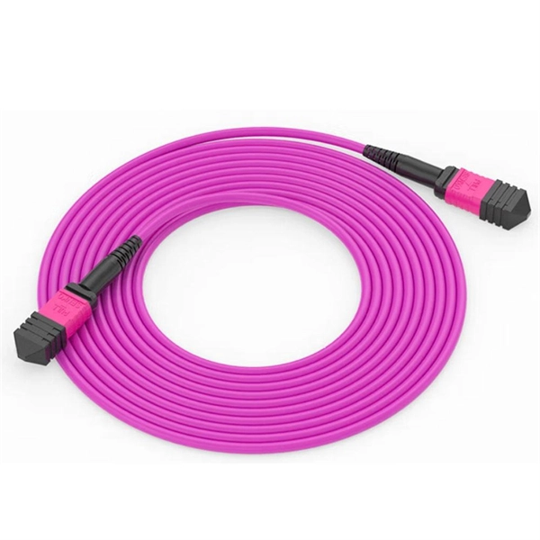
At first glance, a fiber pigtail looks similar to a fiber patch cord. However, there are key differences that matter both technically and commercially. Structural Difference Pigtail: Connector on one end, bare fiber on the other. Executive Summary: A fiber optic pigtail is one of the most commonly specified yet least understood components in structured cabling. Get the wrong connector type, the wrong polish, or skip proper fusion splicing technique—and you're looking at elevated signal loss, increased back reflection, and a. A fiber pigtail is typically a fiber optic cable with one end factory pre-terminated fiber connector and the other exposed fiber. It is usually suitable for field termination using a mechanical or fusion splicer. Compared with quick termination or epoxy and polish connections placed on the field. A fiber optic pigtail is a short length of optical fiber —typically 0. The connector end is polished and tested under factory conditions, ensuring low insertion loss and high return loss. The bare fiber end. While both are essential for linking fibers to devices or other cables, they serve distinct purposes and are designed for specific scenarios. This creates a stable and reliable connection between network equipment.
[PDF]

It is usually welded or threaded, and the two flanges are joined together by bolting them with gaskets to provide a seal, providing easy access to the piping system. A pigtail serves as a bridge between multiple conductors and a single terminal. These short wire segments solve space constraints in junction boxes by creating a central hub. Imagine three wires needing to. This is where the pigtail connector becomes an essential solution. A pigtail connector is a short length of wire with a factory-terminated connector on one end and bare, exposed wires on the other. It serves as a bridge, allowing technicians to repair specific connection points without disturbing. What is a Flange? Flanges are devices used to connect pipes, valves, pumps, fittings, and other equipment such as filters and pressure vessels. It ensures a secure connection by combining wires with a wire connector, like a twist-on connector or a wire nut, and then linking them to the intended terminal or fixture. Pigtails serve. Pigtail connections are most frequently used to ground a switch or electrical outlet and for electrical devices that need to connect to multiple circuit wires. They also come in handy to lengthen circuit wires that are too short to reach a device. It provides a plug-and-play repair solution that restores OEM fit, seal, and electrical reliability.
[PDF]

Long Expansion Cycle: Optical fiber preform production has high technological barriers, and the expansion cycle can take as long as 18-24 months. Even if manufacturers start expanding immediately, the new capacity will not be available until at least 2027. This phenomenon is the result of multiple factors, including tight supply of optical fiber preforms (preforms), long expansion cycles for optical fiber production capacity, and the explosive growth of emerging applications such as AI computing power and drones. The expansion cycle of optical fibers is generally less than 6 months, and fiber optic cables can take 3 months. The expansion of production requires the purchase of equipment and the construction of factories. At the heart of this transformation lies fiber optic cable manufacturing, a precise and sophisticated process that powers our interconnected world. With the global fiber optic market reaching $6 billion and growing at 10% annually, the need for high-quality manufacturing solutions has never been. The manufacturing process of fiber optic cables involves several intricate steps that culminate in the production of high-performance data transmission solutions. This process begins with the creation of a preform, which serves as the foundation for the optical fibers within the cable. This intricate process combines cutting-edge technology, precise engineering, and.
[PDF]
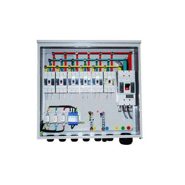
This video shows real on-site footage of electrical installation, demonstrating safe and standardized wiring methods used by professionals. more Learn how to wire a distribution box step by step!. A distribution box is the heart of any electrical system. It takes the incoming power and safely distributes it to different circuits throughout your building. Whether in a home or an industrial facility, this box keeps your electrical setup organized, functional, and efficient. However, the key to. In modern electrical systems, cable distribution boxes (also known as electrical distribution boxes or distribution boxes) play a crucial role as the key hub for managing, distributing, and protecting circuits. It serves as a central hub for distributing electricity throughout a building, ensuring that power is delivered safely and efficiently to all the required locations. Box installation: Make sure that Distribution box has been correctly installed and fixed. Material preparation: Prepare the required circuit breakers, wires, wiring ties and other materials, and ensure that they meet the design drawings and installation requirements. Location determination:.
[PDF]

The optical power meter is similar to the voltohmmeter in application but measures the optical resistance (losses measured in dBm or dBM) of a cable before and after installation and provides a comparative analysis of the splices. The range of the meter is adjustable. Regularly testing fiber optic cables helps minimize network downtime, lengthens the network's longevity, reduces maintenance requirements, and helps support network reconfiguration and upgrades. These factors significantly add to the fiber optic network's long-term performance, manageability, and. Several types of tests are commonly conducted to assess and maintain the health of fiber optic networks. Continuity testing verifies that the fiber is intact and that light can pass through from one end to the other without any blockages. These test procedures assess the physical and functional qualities of fiber optic cables, connectors, and the network as a whole. Key tests include: Effective fiber testing utilizes advanced tools such as Optical. One way to test a splice is to use an Optical Power Meter. As the components like fiber, connectors, splices, LED or laser sources, detectors and receivers are being developed, testing confirms their performance specifications and helps. Regular testing of fiber optic cables is not just a preventive measure; it's an investment in the longevity and efficiency of your network. By identifying potential issues early, you can enhance.
[PDF]
This wikiHow article will teach you how to splice a cut fiber optic cable back together with a fiber optic stripper and cutter and a fiber optic crimper. Trim off any frayed or damaged ends of the cable. While a cut or damaged fiber optic cable can temporarily take your network down, it is possible to quickly fix the cable with the right tools. When fiber cables sustain damage, specialized repair techniques help restore connectivity and maintain data integrity. This comprehensive guide outlines professional fiber optic repair protocols that align with industry best practices. Adhering to precise methodologies, we can mend impaired cables. Get your fiber optic cable repair tools together. You'll need strippers, cleavers, splice trays, a splicing machine, and cleaning materials like alcohol wipes. Leave some extra cable before the damage point. It makes cutting and splicing easier. However, you don't need to panic! It can still be fixed. If you have the right tools and knowledge, you can definitely find the solution. Understanding the causes and types of fiber optic cable damage helps detect. Whether you're a network technician, IT professional, or telecom operator, you'll find practical steps, tools, and tips to restore connectivity with minimal loss. Dekam Fiber's state-of-the-art solutions, including our UltraRepair kits, make these processes accessible and reliable.
[PDF]

Start by separating your Ethernet cable into two separate cables and connecting them to the back of the Ethernet cable splitter. Once the cables are securely connected, connect the other ends to your desired devices. Ensure that the cables are tightly secure and that all connections. When you need to connect multiple wired devices like computers, printers, and IP phones, but only have one Ethernet wall port, using an Ethernet splitter or network switch can expand your connectivity without rewiring. This guide explains your options and helps you choose the best solution for your. An Ethernet splitter is a small device that allows two Ethernet-connected devices to share a single cable run. It does not increase speed or create extra bandwidth. It simply divides signal pairs. This tool works best in basic setups where running another cable is not possible. An Ethernet splitter. Ethernet cable splitter wiring diagrams are essential for anyone who needs to connect multiple devices in a home or office network. With the ever-increasing popularity of high-speed internet and streaming services, providing reliable connections to multiple devices is becoming increasingly. An Ethernet splitter doesn't actually split a single Ethernet connection to provide separate internet access to two devices. Instead, it utilizes only two of the four pairs of wires within a single Ethernet cable to connect two devices, requiring two splitters for the setup to function correctly.
[PDF]
In this guide, we'll break down the key wiring layout, main control panel components, and how everything connects — from the main power isolator to the PLC and sensors on the production line. Every roll forming machine relies on a precisely designed electrical control and wiring system. This system ensures that motors, sensors, drives, and. This guide will walk through the key points you need to consider when preparing electrical schematics and wiring diagrams for a roll forming machine. This guide breaks down the entire electrical system of a modern roll forming machine — from incoming 3-phase supply to flying shear synchronization — with: A complete roll forming electrical system contains: Roll forming machines are typically built for: Voltage mismatch damages VFDs, transformers. Electrical design is the backbone of any roll forming line. Electrical design is the backbone of any roll forming line. These machines convert metal coil.
[PDF]

It operates by emitting a bright and visible red laser light into the fiber and detecting the location of faults by observing the light leaking out of the fiber. It is also possible to locate faults in OTDR dead zones and perform fiber identification from one end to the other. When it comes to testing fiber optic cables, a Visual Fault Locator (VFL) is an essential tool in your toolkit. It's a cost-effective and. Whether you're a seasoned technician or a fiber enthusiast, a VFL is the first step to make your life easier in troubleshooting a fiber optic cabling issue. We will be explaining what The VFL's primary purpose is, and how best to use it. Below are some key use cases for a VFL. It gives instant visual proof of where light escapes the fiber. Even beginners can spot bends, cracks, or bad splices without complex tools. A visual fault locator saves time, cuts stress, and reduces repeat work., optical fiber fault detector, optical fiber fault test pen) is a 650nm (± 20nm) semiconductor laser as a light-emitting device, which emits stable red light through a constant current source drive, and connects with the optical interface into the optical fiber, so. In the world of fiber optic communication, diagnosing and troubleshooting network issues is essential to maintain smooth connectivity. Whether you are a beginner or a professional working with fiber optics.
[PDF]
It is relatively affordable, especially when considering its durability and long lifespan. Additionally, it requires minimal maintenance, reducing ongoing costs. It is generally easy to install and can be quickly integrated into different systems or structures. Cable Tray is often a cost-effective solution compared to other materials. However, since this design is open, it. Cable tray pricing depends on materials, coatings, size, supplier margins, and order quantity —plus hidden costs like shipping and installation. This guide breaks down everything buyers need to know, from price trends to cost-saving tips. Additionally, these solutions help ensure compliance with fire safety codes and regulations, fostering a safer environment. Ensure your infrastructure's safety with NewReach Fire Rated. Lightweight: GRP cable trays are significantly lighter than metal cable trays. Electrical Insulation: GRP cable trays provide excellent electrical insulation. The landscape is shaped by regional manufacturing dominance and evolving buyer preferences. The market is growing steadily, driven.
[PDF]
The QSFP28 optical transceiver module is designed for use in 100GBASE Ethernet throughput up to 100km over single mode fiber (SMF) using a wavelength of 1310nm via duplex LC connectors. The 100 Gigabit Ethernet signal is carried over four wavelengths multiplexing and demultiplexing of the four. 100G ZR4+ optical module provides up to 103. 12Gbps data rate using QSFP28 footprint at the wavelengths of LWDM, which is designed with digital diagnostic monitoring. All Rights Reserved. GigOptics is a leading supplier of Optical Transceivers in the USA. We offer a wide range of products at great prices with fantastic service (SFP, SFP+, SFP28, QSFP+, QSFP28, XFP, etc. Various Switch Tests: Each module is quality tested for compatibility in the multi-brand switches. Comprehensive Testing: Each. The 100GBASE-ZR4+ QSFP28 delivers 100 km reach over single-mode fiber without external amplification. With a 34 dB link budget (FEC enabled) and integrated SOA receiver, this is the longest-reach 100G option in the QSFP28 form factor. 4 LAN WDM lanes at 103.
[PDF]

This article provides a comprehensive guide on how to capture network packets on a switched network using Wireshark, covering key concepts such as port mirroring, network tapping, and other methods to ensure you can monitor traffic effectively on a switched network. Packet capture is supported on the Cisco Catalyst 9300 Series Switches. The following sections provide information about the prerequisites for configuring packet capture. Before starting a Wireshark capture process, ensure that CPU. Embedded Packet Capture (EPC) is an embedded system management tool used for tracking and troubleshooting network packets. This tool helps network administrators capture packets entering and leaving Cisco devices. EPC can be used with Access Control Lists (ACLs) to filter specific packets based on. Packet capture and packet analysis are made possible by the multi-step packet capture protocol (PCAP), which makes use of many tools. Packet sniffers are tools used to do packet capture; they are the first step in the process. They are. Of course switches work on an entirely different principle and do not replicate unicast packets out of every port on the switch, but keep them isolated unless it's a broadcast or multicast. In traditional hub-based. This enables us to easily take captures directly from the switch and export them for analysis. The process is very straightforward and only takes a couple of minutes to set it up. The packets are then stored.
[PDF]
