They directly point to the module type. Additionally, observing the color of the optical module's pull tab is a straightforward way to check it. Multimode: Pull tabs are typically black. Another very direct method is checking the. How to distinguish whether an optical fiber module is single-mode or multi-mode? Optical modules are core photoelectric conversion components in fiber-optic communication, data centers, enterprise networks, and telecom transmission systems. Correctly distinguishing single-mode and multi-mode. Understanding whether your SFP module is single-mode or multimode is crucial in network design. The choice impacts the transmission distance, data rate, and cost of your setup. Typically, single mode SFP modules are labeled as "SM" or "single mode," while multimode modules may be labeled as "MM" or "multimode. ". To determine whether the SFP module in your hand is single-mode or multi-mode, the most straightforward method is to check the color of the pull ring, for example, blue pull rings and red pull rings are single mode, and black pull rings are multimode. Multimode (MMF) SFP modules involves a cross-referencing protocol of physical bail colors, EEPROM telemetry, and wavelength specifications. Precise verification prevents "Ghost Links" and Mode Field Diameter (MFD) mismatches that degrade 800G AI fabric performance.
[PDF]

Connect the red wire to the copper wire with the red color bar of the optical/electrical composite cable, and connect the black wire to the other copper wire of the optical/electrical composite cable. Then press and secure the crimp tube. Ensure that no copper. The composite fiber optic cable is a type of cable that combines both fiber optic and copper conductors within a single cable sheath. This hybrid construction allows for the simultaneous transmission of data using fiber optics and electrical power or additional data using copper conductors. How to Use the Composite Fiber Optic Cable? To begin, you need to gather all the accessories and equipment required: 1. Waterproof Industrial-Grade Fiber PoE Media Converter Compatible with the IEEE802. Cut the cable along the center and pull one copper cable on the left and right sides to the position shown in the figure to expose the optical fiber. Whether you're a seasoned technician or a beginner, this guide has something for everyone. more In this video, we'll walk you. In a previous blog, we covered what to do when you need to connect a device that is located beyond the 100-meter distance requirement and described four ways to address the problem—a new TR, the use of an extender device, extended-reach copper cable and fiber. This article will guide you through the necessary tools, materials, and methods on how to connect fiber optic cables effectively.
[PDF]
An optical module is a typically hot-pluggable optical transceiver used in high-bandwidth data communications applications. Optical modules typically have an electrical interface on the side that connects to the inside of the system and an optical interface on the side that connects to the outside world through a fiber optic cable. The form factor and electrical interface are often specified by an int. Electrical Interface TypesThere have been multiple variants of the electrical interface of optical modules that have been used over the years. The earliest forms of optical modules had an analog electrical interface. In the transmit dir. Many different forms of optical modulation and multiplexing have been employed in optical modules. The most common modulation technique historically has been or NRZ.
[PDF]

Check the diagnostic information, which shows that the received optical power is low, with a threshold of -3 to -23. 01, currently at -22. Once it exceeds the threshold, an alarm will be triggered. Troubleshoot the link, and if the link is normal, replace the optical module. The receive power of an optical module is too low. Indicates the MIB object ID of the alarm. The device management or driver software has a bug. Use an optical power meter to check whether the transmit optical power of the optical module is normal. Remove and. When an optical module is running on a switch, it is often necessary to read its internal information to check the operating status, including link status, real-time Tx/Rx optical power, and temperature. Verifying module identification also helps confirm coding compatibility between the module and. The optical module on the port generates an alarm. Built into modern SFP/SFP+/ SFP28 /QSFP family modules and standardized by SFF-8472, DDM/DOM exposes real-time values for the module's temperature, supply. This chapter gives a description, severity, and troubleshooting procedure for each commonly encountered Cisco NCS 1001 alarm and condition. When an alarm is raised, refer to its clearing procedure. Default Severity: Critical (CR), Service Affecting (SA) Logical Object: EQUIPMENT The 0/PM [0|1] Unit.
[PDF]

This high-quality H3C Networks SFP-XG-SX-MM850-A Compatible 10GBASE-SR SFP+ 850nm 300m DOM Transceiver. A cost-effective solution that provides high bandwidth and transmission rates over short distances. Each transceiver is 100% optically inspected and tested for compatability before. Optical modules transmit signals over optical fibers. H3C devices support optical module models of different specifications. The. This H3C SFP-XG-SX-MM850-D transceiver is high performance and cost-effective SFP+ supporting data-rate of 10. 3125Gbps (10GBASE-SR) or 9. This transceiver is compliant with SFF-8431, SFF-8432 and IEEE 802. Digital diagnostics monitoring is available via a 2-wire serial interface, as specified in SFF-8472. Usually issued within 24 hours. See exceptions May apply, not eligible for free return. See details At any of our 50,000 US locations. See more product details Help others learn more about this product by uploading a video! 0. 76 ounces UBJFMAC B0GQMGC6MR UBJFMAC February. New original H3C 10G multimode optical module SFP-XG-SX-MM850-E 850nm 10G LC interface The H3C 10GBASE-SR SFP+ Optical Transceiver, MMF 850nm, 300m, Industrial Temp is guaranteed 100% Compatible and Functional in its intended equipments. Every SFP-XG-SX-MM850-E is environmentally tested in its.
[PDF]
SFP transceivers are available with a variety of transmitter and receiver specifications, allowing users to select the appropriate transceiver for each link to provide the required optical or electrical reach over the available media type (e.g. or copper cables, or cables). Transceivers are also designated by their transmission speed. SFP modules are commonly available in se.
[PDF]
An optical power meter (OPM) is a device used to measure the power in an signal. The term usually refers to a device for testing average power in systems. Other general purpose light power measuring devices are usually called,, power meters (can be sensors or ), or lux meters. A typical optical power meter consists of a , measuring and display. The sens.
[PDF]

The STAR Module enables thermal and structural deformation data from FEA packages to be imported directly into OpticStudio where the impact on the performance of your optical system can be analysed. Articles in this section provide guidance on using the Ansys Zemax OpticStudio Enterprise-only feature: STAR. STAR tools allow you to integrate deformation, thermal, and stress effects into your optical design. When you use STAR to import structural FEA data onto a diffractive surface. When constructing fiber-optic transmission lines, the optical cable during the installation and installation process is inevitably subject to external mechanical influences. After completion of construction, especially in regions with significant seasonal temperature fluctuations, residual. Thermo-optical simulation is an important extension of classical ray-tracing because many applications, especially in laser technology, have to deal with thermal effects. This enables a deep understanding of the behaviour of your system. Optical beam deflection is a popular method to measure the deformation of micromechanical devices. We present a method to evaluate precisely these parameters, using the relative amplitude of.
[PDF]

800G OSFP DR8/DR8+ (Siph) Product Features 1. Optical Interface Protocol: IEEE 802. 3cu 8X 100GBASE-DR 2. Form Factor: OSFP MSA 4. Power Consumption: <18. FS 400G QSFP-DD module solutions featuring high-performance, high-bandwidth, and cost-effectiveness, are ideal for 400GbE and data centres. QSFP (Quad Small Form-Factor Pluggable) optical modules emerged to meet this demand, becoming a pivotal technology for data center interconnects due to their compact size and exceptional performance. From the initial 40G to today's 800G, the QSFP family has continuously evolved, driving the. Cisco QSFP-DD and OSFP 800G ZR/ZR+ digital coherent optics modules enable 800G traffic over amplified Dense Wavelength-Division Multiplexing (DWDM) links up to 120 km for 800ZR and over 1000 km for 800G ZR+. Explore QSFPTEK's lab through a 360° tour, revealing full transceiver testing. Learn how QSFPTEK provides SMB enterprise and data center network solutions to global customers. Help center for. Your request has been submitted successfully. Our sales manager will contact you soon. High-density 800G OSFP and QSFP-DD transceivers support InfiniBand and RoCE, enabling 100m to 2km transmission via MMF and SMF. Get advice, answers, and solutions when you need them. For general questions, email us at hpestore. com Find an authorized reseller, service provider, or support partner to get a quote.
[PDF]

Single fiber modules (BiDi) use one fiber for both transmitting and receiving data. This saves space and money. They are easier to set up and give steady communication. They use a thin fiber. Pioneer LX305 only has 1 optical input, can I add another with some kind of splitter? I love my new receiver but I need a second optical input and I'm wondering what my options are in this regard. Can anyone help? Thanks in advance. Edit: Everyone is going to ask this question, so here are my. The single-mode optical fiber is designed and engineered to carry one single light mode in a minimal core diameter. It is specified as the best for especially long-distance applications than multimode fiber. Due to its. The optical module serves as a crucial component in optical fiber communication systems, operating at the physical layer, which is the lowest layer in the OSI model. Its primary function is to achieve optoelectronic conversion by converting electrical signals into optical signals and vice versa. An. There are single-fiber and dual-fiber optical transceivers. How do we choose, and what are their differences and advantages? Let's learn about this! What is a Single-Fiber (BiDi) Transceiver? Single fiber module also called BiDi transceiver or WDM module.
[PDF]

They mainly consist of optoelectronic components (such as optical transmitters and receivers), functional circuits, and optical interfaces, aiming to achieve the functionalities of optical-to-electrical and electrical-to-optical signal conversion in optical fiber communication. As an essential component of optical fiber communication, optical modules are optoelectronic devices that facilitate the conversion between optical and electrical signals during the transmission process. Operating at the physical layer of the OSI model, optical modules are core devices in optical. Modern communication networks rely on optical transceivers to transfer data at the speed of light. Whether in 5G base stations, hyperscale data centers, or long-haul telecom networks, these modules convert electrical signals into optical ones — and back again — to ensure fast, stable, and. Optical modules are compact devices that convert electrical signals into optical signals and vice versa. They are used in fiber optic communication systems to transmit data over long distances with minimal loss and interference. These modules typically consist of a laser or LED transmitter, a. That is, metal medium communication represented by coaxial cables and network cables is gradually being replaced by optical fiber media.
[PDF]

Wavelength does not exist independently; it is deeply related to the physical structure and type selection of optical fibers and directly affects key performance indicators such as attenuation and dispersion. The wavelength and transmission distance are important parameters of optical modules, and the transmission distance varies with different wavelengths. So, what is the relationship between wavelength and transmission distance? Is wavelength a factor affecting the transmission distance of optical. Unlike general optical modules with two ports (Tx and Rx), BiDi optical modules have only one optical port and use wavelength division multiplexing (WDM) technology to transmit and receive optical signals of different center wavelengths over the same fiber. BiDi optical modules must be used in. Light's properties are at the heart of any optical transceiver module. Key parameters include center wavelength, spectral width, linewidth, and side-mode suppression ratio (SMSR). The center wavelength determines the operational band, aligned with low-loss windows in silica fiber. Common wavelengths include 850nm, 1310nm, and 1550nm. That value determines whether the module is designed for multimode fiber (MMF) or single-mode fiber (SMF), how much attenuation the signal will experience, how dispersion behaves over distance, and. As the core physical parameter of optical fiber transmission, wavelength also determines the transmission performance of optical networks.
[PDF]

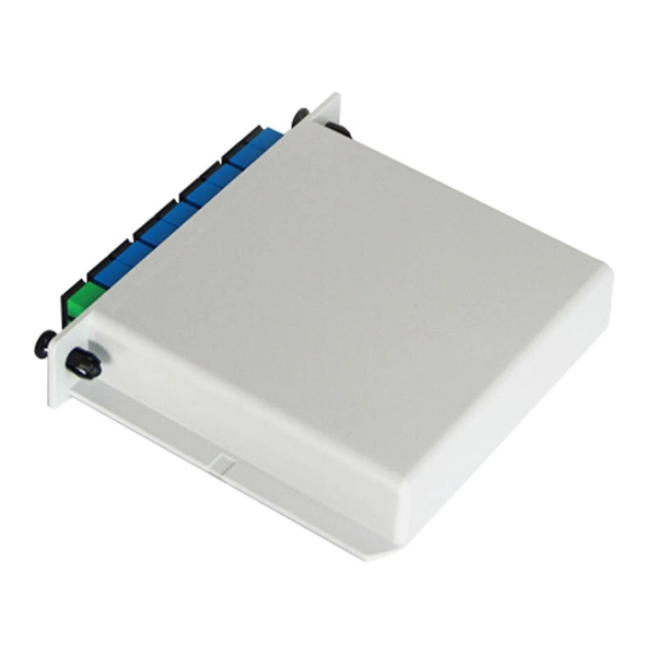
Optical couplers can split or join signals in fibers. You can connect many users to one port with 1:n or 2:n splitters. These devices work both ways, which helps strong network communication. They help send. This small device connects or joins optical fibers together. It helps networks grow and change when needed. Learn about the two main types of fiber optic couplers: fused and planar. Fused. How to Choose the Right Fiber Coupler (FTTH, Data Center & More) Are you in the process of designing a Fiber to the Home (FTTH) network, but wondering how to split one fiber for multiple users? Or maybe you are operating a data center, and you would like to use a single signal to provide to. Fiber optic couplers are optical devices that connect three or more fiber ends, dividing one input between two or more outputs, or combining two or more inputs into one output. The device allows the transmission of light waves through multiple paths. Fiber optic couplers can either be passive or. A fiber optic coupler is a passive optical component that splits, combines, taps, or redistributes light between optical fibers. In real-world networks, couplers let one signal reach many users, allow several signals to share one fiber path, or sample a small amount of light for monitoring. 5/125 µm fiber, with low insertion loss and a broad operating wavelength range from 800 to 1600 nm. The 1x2 and 2x2.
[PDF]