
The Optical Time Domain Reflectometer (OTDR) is useful for testing the integrity of fiber optic cables. It can verify splice loss, measure length and find faults. The OTDR is also commonly used to create a "picture" of fiber optic cable when it is newly installed. The Contractor tasked to perform testing or splicing on any fiber optic cable will follow these testing standards to fulfill their contractual obligations. The Contractor must utilize the correct equipment and testing techniques to gain acceptance, or the work cannot be approved. Later, comparisons can be made. For every fiber optic cable plant, you will need to test for continuity, end-to-end loss and then troubleshoot the problems. If it's a long outside plant cable with intermediate splices, you will probably want to verify the individual splices with an OTDR also, since that's the only way to make. ic system. Fiber optic testing of a newly installed system not only verifies that the system meets its design requirements, but also creates a performance baseline for all future testing and troubleshooting of t at system. What is Fiber Optic Splicing and Why is it Needed? – #1. Use and Maintain Your. This guide reveals the secrets to fusion splicing with little fluff—just proven, straightforward techniques refined from years of work in the field. The guide provides the complete workflow, covering safety precautions, tool selection, fiber preparation, fusion operation, quality control, and.
[PDF]

Main cost drivers include on-site labor, specialized fusion splicing, testing, and any necessary restoration of network performance. This guide provides practical cost ranges in USD with clear low–average–high estimates to help budgeting and planning. Fiber optic splicing costs vary widely depending on project size, location, fiber type, and site conditions. For most commercial projects, expect to pay $50–$150 per fusion splice point — but that number can swing in either direction based on the factors below. The "per splice" rate is the most. There are two primary methods of splicing fiber optic cables: fusion splicing and mechanical splicing. Each method has distinct characteristics and costs associated with it. Fusion Splicing: This method involves aligning two fiber ends and using an electric arc to melt them together, creating a. Adtell Integration is capable of supporting your fusion splicing requirements whether they require Singlemode, Multimode, or Ribbon Splicing. Fusion Splicing Services: Contractor/Customer Fusion Splicing & Installation Services: Adtell integration offers nationwide fusion splicing services. Specifically fiber used for internet. -W2 employee for a decent size telecommunication contractor, all.
[PDF]

In this guide, you will find a chronological description of the fusion splicing process, the principal technical standards, and answers to the real-life questions network engineers and procurement teams may have. 📦 For purchasing, use the RP Photonics Buyer's Guide for fusion splicers. It provides an expert-curated supplier directory, buyer-focused technical background information, and structured selection criteria to support professional procurement decisions. This article explains the principle of fusion. Fusion splicers play a crucial role in the field of optical fibre communications by enabling the permanent bonding of two strands of glass fibre to create a continuous pathway for light to travel through. This process is achieved through precise alignment and fusion of the fibre ends using an. Fusion splicing is the process of fusing or welding two fibers together usually by an electric arc. Fusion splicing is the most widely used method of splicing as it provides for the lowest loss and least reflectance, as well as providing the strongest and most reliable joint between two fibers. Each splicer is equipped with a cleaver and stripper, conveniently includes in a single case. The goal is to align the microscopic glass cores (typically.
[PDF]
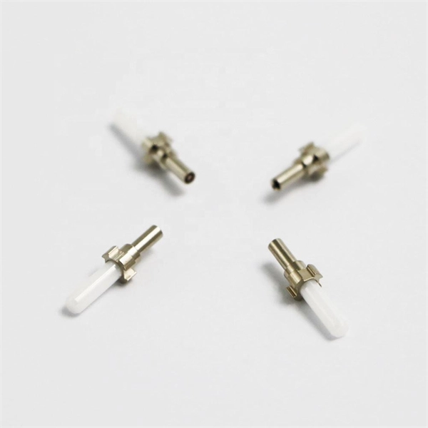
When the heat-shrinkable tube is tightened after splicing, the residual pollutants (such as tiny sand particles) will press the optical fiber and cause the optical fiber to deform, so the splicing loss will increase. At this time, the fiber needs to be cleaned. A fiber optic pigtail is a fiber optic cable with one end terminated with a factory-installed connector and the other end unterminated. As a result, the connector side can be connected to equipment, while the other side is fused in the case of fusion splicing and a mechanical connection in the case. Executive Summary: A fiber optic pigtail is one of the most commonly specified yet least understood components in structured cabling. The guide provides the complete workflow, covering safety precautions, tool selection, fiber preparation, fusion operation, quality control, and. Removes the protective coating to expose the bare fiber for splicing, ensuring no scratches or nicks. Produces a clean, precise fiber end face, critical for low-loss fusion or mechanical splicing. Precisely aligns and fuses fiber ends to form a stable, low-loss connection suitable for long-term. The scientific fiber coiling method can make the optical fiber layout reasonable, the additional loss is small, can withstand the test of time and harsh environment, and can avoid the phenomenon of fiber breakage caused by extrusion. Optic Fiber Management Rules 1. Coil the fibers along the.
[PDF]

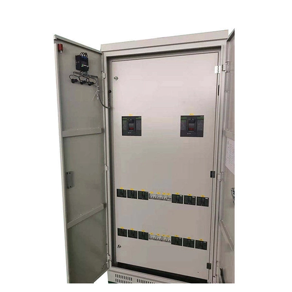
Fiber optic terminal boxes provide functions such as input, branching and splicing of optical fiber cables. Through the connectors and splicing boxes in the terminal box, optical fibers can be quickly connected and repaired. Serving as a critical connection point, FTB facilitates the termination, splicing, or connection of fibers from various cables to other network devices such as switches, routers, or Optical Network Terminals (ONTs). It aids in splicing, splitting, storing, and managing fibers within the appropriate. The optical fiber terminal box is the terminal joint of an optical cable, one end of which is an optical cable, and the other end is a pigtail, which is equivalent to a device that splits an optical cable into a single optical fiber. A fiber pigtail is a specific hardware connection used for cable termination. It is a small enclosure that can house and protect the fiber optic cables, splices, and connectors. The optical fiber termination box and optical fiber splice box serve distinct purposes and are not interchangeable.
[PDF]

It describes three main splicing methods - de-matable connectors, mechanical splices, and fusion splices. Mechanical splices have higher losses than fusion splices. Fusion splicing welds two fibers together using an electric arc and provides the lowest loss. Executive Summary: A fiber optic pigtail is one of the most commonly specified yet least understood components in structured cabling. Get the wrong connector type, the wrong polish, or skip proper fusion splicing technique—and you're looking at elevated signal loss, increased back reflection, and a. Fiber optic cables are the invisible highways of our digital world, carrying massive amounts of data at the speed of light. But what happens when you need to join two cables to extend a network or repair a break? You can't just twist them together. This is where fiber optic cable splicing—the. Fiber Optic Cable is a form of modern network cable that has a far greater capacity than electrical communication connections. Splicing is typically required during cable installation, maintenance, or network expansion. This is essential for extending network reach, repairing breaks, or connecting cables in data centers and telecom infrastructure. The goal is to align the microscopic glass cores (typically.
[PDF]

Splice Diagrams or Matrices capture an electric or optical network inside a location – documenting cables, ported equipment, and connections. Splices are fiber-to-fiber, port-to-fiber and port-to-port. Fiber optic cable splicing involves joining two fiber optic cables together. Another method of connecting optical fibers is termination or connectorization, which consists of processing the end of a fiber optic bundle so that it can be connected to other fibers or devices through fiber optic. In this guide, we cover the basics of fiber optic splicing, how to perform splicing using two different methods, and finally some best practices to perform good fiber splicing. Ensure Your Splicing Tools are Clean – #2. Use and Maintain Your. What to show on a network diagram? Fiber optic network diagrams represent the architecture and connectivity of fiber optic systems, and their design philosophy integrates technical, functional, and conceptual aspects. The diagrams abstract complex details of fiber optic systems to make them. This Geoschematics drawing remains easy to read despite containing more than 2000 fibers and 500 splices. All students and instructors must wear safety glasses in this lab. It is copyrighted by the FOA and may not be distributed without FOA permission. This VHO covers similar material to the videos on YouTube. The lab manual has several.
[PDF]
The operation and skills of fiber optic fusion splicing technology can be mainly divided into five steps: fiber stripping, fiber cutting, fiber melting, fiber sleeve, and fiber winding. In this guide, we cover the basics of fiber optic splicing, how to perform splicing using two different methods, and finally some best practices to perform good fiber splicing. What is Fiber Optic Splicing and Why is it Needed? – #1. And tools used for fiber fusion: fusion splicer; fiber cleaver; cable stripper; fiber optic stripper; alcohol;. Splicing fiber optic cable is an extremely important phase for making dependable, high-speed communication infrastructures. Regardless of the type of fiber network you're deploying, be it for telecom, enterprise data centers, or smart city infrastructure, fusion splicing provides the benefits of. While a cut or damaged fiber optic cable can temporarily take your network down, it is possible to quickly fix the cable with the right tools. In this video, we walk through the essential steps of preparing and splicing a fiber optic cable. Watch the complete process, from carefully stripping the fiber coating and performing a precision cleave, to loading the prepared fiber into the fusion splicer for a perfect alignment. Before jumping into the physical steps, it's important to understand the two primary methods of fiber splicing: fusion splicing and.
[PDF]

This guide covers everything: what fiber optic pigtails are, how they differ from patch cords, which connector and polish type to specify, how to choose between mechanical and fusion splicing, and the real-world applications where pigtails are the right call. In this guide, we cover the basics of fiber optic splicing, how to perform splicing using two different methods, and finally some best practices to perform good fiber splicing. What is Fiber Optic Splicing and Why is it Needed? – #1. Whether you're building out an ODF. Think of a fiber optic cable splice as the seamless stitching that keeps data flowing through the delicate threads of a network—like a master tailor joining fabric with precision. Whether repairing a broken cable or extending a fiber run, fiber optic splicing ensures light signals travel. Fibre optic splicing is an essential skill in the world of modern telecommunications, offering a reliable method to connect optical fibres for seamless data transmission. As the demand for high-speed internet and robust communication networks continues to grow, learning to splice fibre optics is. In this guide, you will find a chronological description of the fusion splicing process, the principal technical standards, and answers to the real-life questions network engineers and procurement teams may have. Therefore, we will also touch on cost factors, risk management, and best practices in.
[PDF]
Fiber optic splicing is the process of joining two fiber optic cables together so that light signals can pass with minimal loss or reflection. Splicing is typically required during cable installation, maintenance, or network expansion. Another method of connecting optical fibers is termination or connectorization, which consists of processing the end of a fiber optic bundle so that it can be connected to other fibers or devices through fiber optic. When deploying fiber optic cabling, one of the most critical decisions is how to terminate the fiber—either by splicing or using connectors. Both techniques have their advantages and are suited for different applications, but understanding which method to use can greatly impact the network's. Fiber optic splicing, crucial for maintaining seamless connectivity in modern communication networks, primarily uses two methods: fusion splicing and mechanical splicing. Fusion splicing provides a low-loss, highly reliable connection by melting and fusing fiber ends, making it ideal for long-haul. As fiber optic connections become increasingly mainstream, the need to connect fiber optic cables to one another — or splicing — is also on the rise. Get the wrong connector type, the wrong polish, or skip proper fusion splicing technique—and you're looking at elevated signal loss, increased back reflection, and a.
[PDF]

A lighting control module operates as the central controller for a lighting system. It receives input from switches, apps, or sensors and regulates electrical flow to connected lights. Depending on the setup, it adjusts brightness, color temperature, or full lighting scenes. It acts as a bridge between your physical lighting fixtures and the smart systems that manage them. Instead of relying solely on traditional wall switches, you can control your lights via remotes, mobile or web apps. A lighting control module is an essential component in a lighting control system that manages how lights are powered, dimmed, or switched on and off. Think of it as the “brain” that receives commands—either from a manual switch, a sensor, or a building automation system—and translates them into. A lighting control module is a smart device that manages lighting circuits, adjusting brightness, automating schedules, and responding to sensors. It enhances comfort, efficiency, and ambience in homes and commercial spaces. Explore the multifaceted benefits and applications of lighting control modules, from home automation to industrial. These modules are designed to communicate with various sensors, switches, and control panels, making lighting adaptable to different environments and user preferences. It enables precise management of lighting systems, allowing for adjustments in brightness, color, timing, and even integration with other smart devices. This innovation.
[PDF]

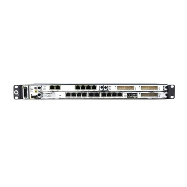
An optical network is a communication system that leverages light to convey information across distances, encoding data into rapid flashes of light instead of relying on electrical voltage changes. At the heart of this ecosystem lies the Optical Transport Network (OTN) — a framework defined by the ITU-T (notably G. 709) that has become the foundation for modern optical communications. This method allows engineers to manage the exponential growth in global data traffic generated by. A passive optical network (PON) is a system commonly used by telecommunications network providers that brings fiber optic cabling and signals all or most of the way to the end user. Depending on where the PON terminates, the system can be described as fiber to the curb, fiber to the building or. An Optical Transport Network (OTN) is a transmission network based on wavelength division multiplexing (WDM) technology. It is a specific type of transmission network that transmits data and manages it using optical signals. OTN is built on a series of protocols, including G. It is designed to provide a high-speed, scalable, and reliable infrastructure for the transmission of data between different network nodes. While there are many subtle differences, a clear distinction between active optical networking and PON topology is PON's use of a.
[PDF]

Insertion loss tells you how much weaker the signal becomes after passing through the splitter. Let's say you have a laser output at 0 dBm (which is 1 milliwatt of optical power). If you use a 1×8 splitter with ~10. 5 dB of insertion loss, the power at each output would be: 0 dBm – 10. 5. Enter excess loss from the splitter datasheet for your wavelength. Add connector and splice quantities with realistic planning losses. Include any additional component losses and an engineering margin. Enable power budget to estimate received power and margin. Press Calculate to show results above. Understanding optical splitter loss isn't just about plugging numbers into a calculator. It's about knowing what factors contribute to that loss, how manufacturers specify it, and how it impacts the overall performance and reach of your network. Ignore it, and you might find your signal too weak to. Optical insertion loss refers to the signal loss resulting from the insertion of components such as connectors or splices in an optical fiber system. Common ratios: For cascades, add losses and validate margin using the Optical Budget tool. This Fiber Optic Splitter Insertion Loss is the splitter devices loss, Considering fiber connectors or connectors+adapter insertion loss in LGX, The fiber splitter IL would be a little bigger. To make clear the basic ftth fiber splitter loss in performance, You can refer to the below loss chart.
[PDF]