
Data centers are the backbone of the AI revolution. Explore if data center stocks are a good investment for your portfolio growth and insights on how to invest wisely. Investment in data centers has grown to $197 billion in 2024, making this sector one of the fastest-growing commercial real estate niches. Data center investors are so drawn to this segment's steady utility-like cash flow and favorable risk-adjusted returns that in 2021, the sector saw 209 deals. These facilities provide the physical space, secure environments, uninterruptible power supplies, and advanced cooling systems required to run servers, storage arrays, and networking equipment for cloud providers, enterprises, and AI developers. The global data center market is large, and highly. They're the massive, climate-controlled buildings packed with servers that make cloud computing, streaming, ecommerce, and AI even possible. And right now, demand for them is exploding. That demand isn't just from tech giants looking to store your photos or keep your Netflix queue running.
[PDF]

Organizations expanding their IT footprint face critical decisions around infrastructure, availability, and cost. The benefits of data centers extend beyond simple equipment housing, offering growing companies strategic advantages in reliability, scalability, security, and. Their importance stems from several core functions: Data Storage and Processing: Data centers house the infrastructure to store and process the exponentially growing volumes of data generated by individuals, businesses, and governments. This includes everything from personal photos and videos to. The AI data center boom is reshaping economies while straining power grids, water supplies, and communities. Here's the real cost behind AI's rise. When ChatGPT launched in late 2022, I watched something remarkable happen. Within two months, it hit 100 million users, a growth rate that sent. In today's data-driven digital environment, many companies are increasingly relying on data centers to support digital transformation, improve operational efficiency, and meet customer expectations. But in the age of cloud computing, artificial intelligence, and the Internet of Things (IoT), a data center is far more than just a physical storage space for hardware. It is the beating heart of the digital economy, enabling everything from storing vast amounts of data to powering websites, apps.
[PDF]

In this guide, we'll walk you through exactly how to splice fiber without a fusion splicer, covering the tools you need, the step-by-step process, performance specs, and common mistakes to avoid. By the end, you'll be equipped to make clean, low-loss connections in any. In this guide, we cover the basics of fiber optic splicing, how to perform splicing using two different methods, and finally some best practices to perform good fiber splicing. What is Fiber Optic Splicing and Why is it Needed? – #1. Use and Maintain Your. Optical fiber fast connectors, also known as cold connectors, are becoming increasingly popular due to their ease of use and quick installation. Unlike traditional fiber connectors that require epoxy and polishing, fast connectors use a mechanical splice to join the fibers. What is a. Three methods for connecting two fiber optic cables: fusion splicing, mechanical coupler, and splicing. Whether repairing a broken cable or extending a fiber run, fiber optic splicing ensures light signals travel. Fiber optic splicing is the art and science of joining two separate optical fibers to create a continuous light path. This process requires precision, patience, and a deep understanding of the delicate nature of optical fibers. Before any splicing can occur, whether it's mechanical or fusion.
[PDF]
The QSFP28 optical transceiver module is designed for use in 100GBASE Ethernet throughput up to 100km over single mode fiber (SMF) using a wavelength of 1310nm via duplex LC connectors. The 100 Gigabit Ethernet signal is carried over four wavelengths multiplexing and demultiplexing of the four. 100G ZR4+ optical module provides up to 103. 12Gbps data rate using QSFP28 footprint at the wavelengths of LWDM, which is designed with digital diagnostic monitoring. All Rights Reserved. GigOptics is a leading supplier of Optical Transceivers in the USA. We offer a wide range of products at great prices with fantastic service (SFP, SFP+, SFP28, QSFP+, QSFP28, XFP, etc. Various Switch Tests: Each module is quality tested for compatibility in the multi-brand switches. Comprehensive Testing: Each. The 100GBASE-ZR4+ QSFP28 delivers 100 km reach over single-mode fiber without external amplification. With a 34 dB link budget (FEC enabled) and integrated SOA receiver, this is the longest-reach 100G option in the QSFP28 form factor. 4 LAN WDM lanes at 103.
[PDF]
This wikiHow article will teach you how to splice a cut fiber optic cable back together with a fiber optic stripper and cutter and a fiber optic crimper. Trim off any frayed or damaged ends of the cable. While a cut or damaged fiber optic cable can temporarily take your network down, it is possible to quickly fix the cable with the right tools. When fiber cables sustain damage, specialized repair techniques help restore connectivity and maintain data integrity. This comprehensive guide outlines professional fiber optic repair protocols that align with industry best practices. Adhering to precise methodologies, we can mend impaired cables. Get your fiber optic cable repair tools together. You'll need strippers, cleavers, splice trays, a splicing machine, and cleaning materials like alcohol wipes. Leave some extra cable before the damage point. It makes cutting and splicing easier. However, you don't need to panic! It can still be fixed. If you have the right tools and knowledge, you can definitely find the solution. Understanding the causes and types of fiber optic cable damage helps detect. Whether you're a network technician, IT professional, or telecom operator, you'll find practical steps, tools, and tips to restore connectivity with minimal loss. Dekam Fiber's state-of-the-art solutions, including our UltraRepair kits, make these processes accessible and reliable.
[PDF]

See this topic to learn how to remove and install a door. Unlock and open the door. Removing a door Hold the door in place, and lift both hinge pins until they lock in the open position so that the door is disengaged. Remove the door from the rack cabinet frame. Install. Before installing your server in a rack cabinet, review the following guidelines: Two or more people are required to install the device in a rack cabinet. Ensure that the room air temperature is below 35°C (95°F). Do not block any air vents; usually 15 cm (6 in. ) of space provides proper airflow. In this comprehensive guide, we will walk you through the step-by-step process to ensure a successful installation and setup of your network cabinet system. Key steps include measuring the installation area, mounting rails, organizing cables, and testing stability. Proper grounding and compliance with safety. Page 3 M3. Click Side Panels (E) into place. To install the Tempered Glass Door (G), locate the side with two pins. With your thumb, pull down on the spring pin and slide it. Complete Assembly Procedure for 9U Wall Mounted Network Cabinet (Double Section) How to assemble a double section wall mounted network cabinet server rack? 1, Insert top and bottom panels into the side frames. And fixed the frame on the front door position with 4 M5*8 self-tapping screws.
[PDF]

This article provides a comprehensive guide on how to capture network packets on a switched network using Wireshark, covering key concepts such as port mirroring, network tapping, and other methods to ensure you can monitor traffic effectively on a switched network. Packet capture is supported on the Cisco Catalyst 9300 Series Switches. The following sections provide information about the prerequisites for configuring packet capture. Before starting a Wireshark capture process, ensure that CPU. Embedded Packet Capture (EPC) is an embedded system management tool used for tracking and troubleshooting network packets. This tool helps network administrators capture packets entering and leaving Cisco devices. EPC can be used with Access Control Lists (ACLs) to filter specific packets based on. Packet capture and packet analysis are made possible by the multi-step packet capture protocol (PCAP), which makes use of many tools. Packet sniffers are tools used to do packet capture; they are the first step in the process. They are. Of course switches work on an entirely different principle and do not replicate unicast packets out of every port on the switch, but keep them isolated unless it's a broadcast or multicast. In traditional hub-based. This enables us to easily take captures directly from the switch and export them for analysis. The process is very straightforward and only takes a couple of minutes to set it up. The packets are then stored.
[PDF]
This article delves into the intricate steps of busbar selection, preparation, and installation, ensuring efficient and safe power distribution. You'll discover the essential tools and techniques. FlexLine® busbars PSX go hand in hand with the flex terminals of the FlexLine® protection devices by following an one-size-fits-all approach. Whenever the neutral conductor terminals are not required, the flex terminals accommodate this busbar pin without any mechanical or electrical connection. BEIENE Smart 3 in 1 Busbar Processing machine is with our Intelligent 3D Busbar Program software Smartnest. From 3D Drawings, your busbar can be processed directly. Also can be optimized the production by the nesting function !. more BEIENE Smart 3 in 1 Busbar Processing machine is with our. 40 mm bar centre distance, 3-pole, space-saving plug-and-lock connection from the front, support suitable for top-mounting, all-round contact hazard protection. Our Mother company was founded in 1955 which is the Top Hydraulic research and developing institute in China! “Say Goodbye to CNC Machine, Open your Intelligent Times” this is our commitment to each customer !.
[PDF]

When it comes to testing fiber optic cables, a Visual Fault Locator (VFL) is an essential tool in your toolkit. A VFL is used to detect faults, breaks, or bends in fiber optic cables by emitting a bright red light that is visible even through the fiber's jacket. It's a cost-effective and. A Visual Fault Locator which can be also called visual fault identifier (VFI), fiber fault locator, fiber fault detector, etc., is a visible red laser light designed to inject visible red light energy into an optical fiber. Using a VFL to diagnose issues can save time and cost when diagnosing an. A visual fault locator is a compact, handheld device that emits a visible light beam, typically in the red wavelength range, through a fiber optic cable. It works by injecting a visible red laser light into the fiber, which can be seen through the jacket or at the end of the cable. If the light doesn't come out the other side, there might be a problem. You. And in the end we will show you how to use an old cell phone's camera to detect light in a fiber optic system. It uses a bright incandescent bulb or visible LED source to.
[PDF]

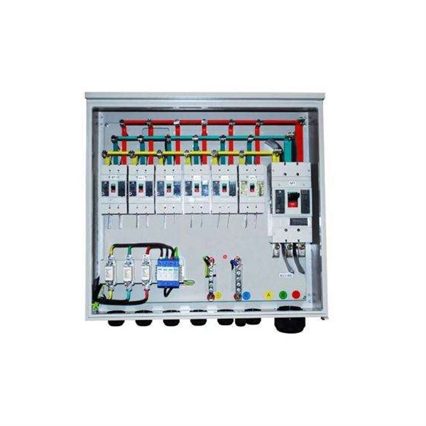
We are offering a comprehensive, fabrication-ready CAD file for a standard electrical distribution box. This isn't just a simple layout; it's a detailed mechanical drawing intended for electrical engineers, panel builders, and fabricators. High-performing, reliable product solutions that transmit data, power and signal in cars, planes, power grids, appliances, electro. Discover all CAD files of the "Power Distribution Boxes" category from Supplier-Certified Catalogs ✅ SOLIDWORKS, Inventor, Creo, CATIA, Solid Edge, autoCAD, Revit. The CAD files and renderings posted to this website are created, uploaded and managed by third-party community members. This content and associated text is in no way sponsored by or affiliated with any company, organization, or real-world good that it may purport to portray. It is running model of. Development of a distribution box for a meter. Download CAD block in DWG. 22 KB). Disassembly of a distribution box of a Perkins engine Already Subscribed? Free download Distribution box in DWG format or CAD block. This component, also known as a breaker panel or consumer unit, is the central nervous system for power management in any residential, commercial, or industrial setting. We design and manufacture a range of electrical products for the distribution, protection, control and management of electrical systems in low voltage environments. We help our customers to design and build their own.
[PDF]

Relay protection is the discipline of designing schemes that detect faults, coordinate relays, and isolate equipment without outages. It emphasizes selectivity, coordination, fault response, and system behavior rather than individual relay devices. Relay protection is often misunderstood as a. A protective relay is an intelligent electrical device designed to detect faults in power systems and initiate corrective actions such as tripping a circuit breaker. : 4 The first protective relays were electromagnetic. This document provides recommendations, background and philosophy on relay protection that is not available in M07. The facilities to which this Document applies are generally comprised of the fol-lowing: In analyzing the relaying practices to meet the broad objectives set forth, consideration must. What is a Protective Relay? A protective relay is an intelligent device that senses abnormal electrical conditions, such as overcurrent, under-voltage, or frequency deviations. It initiates the operation of circuit breakers to isolate the affected section. This prevents damage to equipment, reduces. Protective relays and devices have been developed over 100 years ago to provide “lastline”of defense for the electrical systems. They are intended to quickly identify a fault and isolate it so the balance of the system continue to run under normal conditions. The selection and applications of.
[PDF]

Home and business fiber optics projects typically range from a few hundred to several thousand dollars, depending on run length, fiber type, and labor needs. The main cost drivers are materials, installation time, and environmental factors that affect trenching, conduit, and terminations. Commercial building installations with 100-200 network drops generally range from $15,000 to $30,000. Single-mode fiber costs less per foot than multimode fiber, but it requires more. What is Fiber optic network design? Fiber optic network design involves the planning, routing, and drafting of Fiber cable layouts to support high-speed data transmission. It includes detailed mapping of backbone, distribution, and drop connections for FTTH, FTTP, FTTx, and enterprise networks. Fiber optic network design refers to the specialized processes leading to a successful installation and operation of a fiber optic network. It includes first determining the type of communication system (s) which will be carried over the network, the geographic layout (premises, campus, outside. According to ResearchAndMarkets, the global market for fiber optics was estimated at $5. 8 billion in 2022 and is expected to reach $11. This is the dominant broadband access technology across half of OECD countries today. The price landscape varies from basic drop cables to enterprise backbone runs, with per foot and per reel pricing common in estimates. This guide presents cost ranges.
[PDF]

We propose an optical circulator formed of a magneto-optical cavity in a 2D photonic crystal. With spatially engineered magnetic domain structures, the cavity can be designed to support a pair of counterrotating states at different frequencies. By coupling the cavity to three waveguides, and by. ulator on silicon with 12dB isolation ratio. By locally switching the direction of the magnetic field on chip, we can dynamic es nators; (230 o integrate in photonic integrated circuits. They are widely used in WDM networks, opt cal amplifiers, and optical sensing systems. Previous demonstrations. A three-port circulator for optical communication systems comprising a photonic crystal slab made of a magneto-optical material in which an magnetizing element is not required to keep its magnetic domains aligned is suggested for the first time. Coupled mode theory is used to predict the broadband condition. It is shown that the rod–waveguide coupling. Abstract—In this paper, we propose a development of a T-shaped circulator based on a 2D-photonic crystal, which has a simple and compact structure. This structure makes the non-reciprocal transmission of electromagnetic waves. Through a series of adjustments in the crystalline geometry and using.
[PDF]