
Plan your outdoor fiber installation carefully by surveying the site, choosing the right cable type, and following FOA and OSP standards to ensure reliability. Select the best installation method—direct burial, aerial, conduit, or underwater—based on your environment and. Underground cables are pulled in conduit that is buried underground, usually 1-1. 2 meters (3-4 feet) deep to reduce the likelihood of accidentally being dug up. In extreme cold climates, cables may need to be buried at greater depths where there temperatures are colder and frost penetrates to. We are Jera line, a factory that produces cable infrastructure products. FODB-8 is installed with adapters, splitters, drop cable patchcords, pole bandings, and fiber cable slack storage. Use. pport cables and splice enclosures. Cost of rack Wire Splice B x (200 (50' Mi As ve 1'-0" wide (min) concrete apron. rons shall be sloped away from box. Cost of apron o d oun. FTTP or fiber To The Premises applications have reinforced the importance of reliable and stable fiber optic terminations. Good quality fiber laying and termination systems help achieve minimal back reflection and low signal loss. They also feature resistance to moisture, impact, chemical exposure. Fiber optic cable may be installed indoors or outdoors using several different installation processes. Outdoor cable may be direct buried, pulled or blown into conduit or innerduct, or installed aerially between poles.
[PDF]

A junction box contains four trade size 3 raceways: two on the left side, one on the right side, and one on the bottom. Once conductors have to turn, be pulled through, or be spliced inside an enclosure, the box dimensions start affecting installation time, conductor damage risk, and inspection results. A raceway design that looks fine in a panel schedule can still become a problem if the box is too short for an. Pull boxes, junction boxes, and conduit bodies must be sized to allow conductors 4 AWG and larger to be installed without damage to the conductor insulation. The NEC provides sizing requirements in 314. The distance between raceway entries enclosing the same conductor must be at least 6 times the trade. To size a junction box correctly, first decide whether NEC 314. Use box-fill rules for splices and devices, and pull-box rules for large conductors and raceways. The most common mistake is using the wrong. NEC 314. 28 specifies the minimum size requirements for pull and junction boxes in electrical installations. Proper sizing ensures conductors can be installed without damage and allows for proper bending space. How Does the Calculator Work? The calculator uses NEC 314. Minimum Length = 8 × Largest Conduit Size Minimum Dimension = 6 × Largest +.
[PDF]

#FTTH #Fiber_to_the_Home* Watch this video to see how FTTH Fiber Optic Outdoor Distribution Box for Internet * FTTH Fiber Optic Outdoor Distribution Box இன்ஸ. A fiber termination box is the standard instrument used in fiber optic networks to connect, secure, and protect optical fibers at the terminating point. It functions as a junction between the incoming fiber cable and the outgoing customer-side fiber cable, where one fiber can be spliced, patched. The optical fiber distribution box allows people to easily access the optical fibers in the box, and can well protect the optical fibers. In addition, the drawer structure also facilitates high-density wiring and good cable management. However, because optical fibers are fragile and can be easily. Keeping this page as a placeholder for now. Have any questions? Talk with us directly using LiveChat. A fiber pigtail is a specific hardware connection used for cable termination. Thus, a fiber termination box is used to terminate the optical fiber. Using a fiber distribution box (FDB) enables the reliable transmission of data through fiber optic cables in networks small and large. As networks expand and more homes and businesses require high-speed connectivity, skillfully installing and managing an FDB becomes essential knowledge for any. A Fiber Termination Box, also known as a Fiber Distribution Box, is a crucial component in fiber optic networks. FTBs play a vital role in ensuring the.
[PDF]

In this video, we'll walk you through the process of wiring a home distribution box with a detailed connection diagram. Whether you're an electrician or a DIY enthusiast, this guide will help you understand the basics of home electrical distribution. more Welcome to our channel! In this video. This guide provides step-by-step instructions for connecting a distribution box and highlights key factors to consider during installation. What Is a Distribution Box? A distribution box, also known as an electrical distribution board, is a critical component in electrical systems. It has three categories: residential, commercial and industrial electrical distribution boxes, all of which play important roles in their respective electrical. Understanding how to safely set up the main connections of a home's power distribution system is essential for ensuring reliable and secure operation. A correct installation process minimizes the risk of electrical faults and increases the longevity of your setup. It is usually equipped with circuit breakers, fuses, terminal connectors, and other components. It serves as a central hub for distributing electricity throughout a building, ensuring that power is delivered safely and efficiently to all the required locations.
[PDF]

This video shows real on-site footage of electrical installation, demonstrating safe and standardized wiring methods used by professionals. more Learn how to wire a distribution box step by step! This video shows real on-site footage of. Material preparation: Prepare the required circuit breakers, wires, wiring ties and other materials, and ensure that they meet the design drawings and installation requirements. Location determination: Determine the installation position of the circuit breaker according to the position of the. Learn how to install a distribution box safely and correctly. Covers wiring, placement, standards, and expert tips for a compliant setup. A distribution box is the heart of any electrical system. It takes the incoming power and safely distributes it to different circuits throughout your building. It serves as a central hub for distributing electricity throughout a building, ensuring that power is delivered safely and efficiently to all the required locations. This video highlights the installation process for CANTEX Exposed Weatherproof PVC electrical boxes. When an electrical connection is needed outside of a home, commercial or industrial building---or anywhere it might be exposed to the elements, weatherproof electrical boxes and covers are required. It has three categories: residential, commercial and industrial electrical distribution boxes, all of which play important roles in their respective electrical.
[PDF]

This video shows real on-site footage of electrical installation, demonstrating safe and standardized wiring methods used by professionals. Covers wiring, placement, standards, and expert tips for a compliant setup. A distribution box is the heart of any electrical system. It takes the incoming power and safely distributes it to different circuits throughout your building. In this video, we'll walk you through the process of wiring a home distribution box with a detailed connection diagram. Whether you're an electrician or a DIY enthusiast, this guide will help you understand the basics of home electrical distribution. It has three categories: residential, commercial and industrial electrical distribution boxes, all of which play important roles in their respective electrical. This guide aims to provide a comprehensive overview of double wide mobile home electrical wiring diagrams, covering everything from the main service panel to individual circuits. This panel is. Box installation: Make sure that Distribution box has been correctly installed and fixed. Material preparation: Prepare the required circuit breakers, wires, wiring ties and other materials, and ensure that they meet the design drawings and installation requirements. Location determination:.
[PDF]

Connect the phase and neutral wires from the input power supply to the input of the Main MCB. Learn how to install a distribution box safely and correctly. Covers wiring, placement, standards, and expert tips for a compliant setup. It takes the incoming power and safely distributes it to different circuits throughout your building. Learn how to wire a distribution box step by step! This video shows real on-site footage of electrical installation, demonstrating safe and standardized wiring methods used by professionals. Below is a quick checklist of everything you will need for a safe and efficient installation: Connecting a distribution box involves several steps to ensure proper electrical flow. It is usually equipped with circuit breakers, fuses, terminal connectors, and other components. It is mainly used to isolate fault circuits, prevent overload, and ensure the safe operation of. Box installation: Make sure that Distribution box has been correctly installed and fixed. Location determination:. An electrical panel box, also known as a breaker box or a distribution board, is a crucial component of any electrical system. It serves as a central hub for distributing electricity throughout a building, ensuring that power is delivered safely and efficiently to all the required locations.
[PDF]

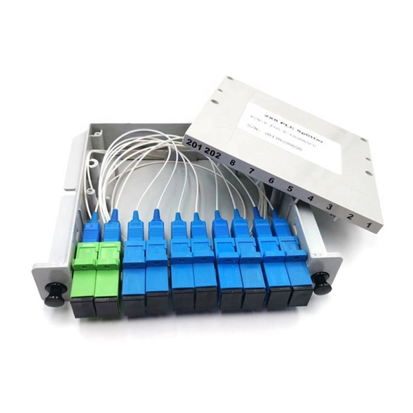
First, connect each pre-terminated fiber optic cable to the adapter panel separately, making sure the ports correspond one-to-one; then fix the fiber optic adapter panel to the front panel of the distribution box with the bend radius control clip. In general, installing the optical fiber distribution box can be divided into three steps: installing the optical fiber distribution box on the rack, introducing the optical cable into the optical fiber distribution box, and planning the optical fiber path in the optical fiber distribution box. The. Bottom installation: Select a proper installation position in the equipment room and drill four holes in the floor according to the dimensions shown in the manual. Fix the rack to the ground with expansion bolts. Top installation: Dimensions of four connection holes on the top according to the. The Optical Distribution Box (ODB) is high-density 2-in-2-out fiber box solution. Designing with a compact size of 340x220x100mm, the cabinet accommodates 1x2,1x4,1x8 and 1x16 etc. The 4 ports are sized for main cable from 9 to 16mm in diameter, along with 16 3mm cables. Accessory Kits:. Install the optical fiber distribution box on the rack. Ensure that the box is installed firmly and horizontally, and the deviation of perpendicularity is not greater than 3mm.
[PDF]
This guide will walk you through every step of the process, from selecting the right materials to securing connections and ensuring safety. Whether you're a seasoned professional or an enthusiastic DIYer, our detailed instructions will equip you with the knowledge and confidence to tackle this. Learn how to properly install an electrical box safely and efficiently. In this step-by-step tutorial, we'll cover: ✅ Tools you need. Covers wiring, placement, standards, and expert tips for a compliant setup. A distribution box is the heart of any electrical system. It takes the incoming power and safely distributes it to different circuits throughout your building. A neutral bar kit is a fundamental component within an electrical service panel, often called a breaker box, designed to manage the flow of electricity in a home or building. This metal strip serves as the termination point for all neutral conductors from the branch circuits. By consolidating these. Before starting the installation, finding a proper place for putting the distribution box is crucial, because it largely decides the safety and convenience of maintenance. Let's see what factors need to be taken care of when choosing the installation place. Beginning of dialog window. Escape will cancel and close the window.
[PDF]
However, with a few simple steps, you can open an outdoor electrical box safely and efficiently. Whether you're an experienced DIYer or a first-time electrician, this guide will show you how to open an outdoor electrical box without putting yourself or your property in danger. The first thing you. Whether you are an electrical contractor or a construction brigade, knowing how to properly and safely install distribution boxes is the basis of ensuring the safe operation of the entire system. This article details the process of installing them, which helps you comprehend distribution boxes. In this video, I'll guide you through the complete wiring diagram for a single-phase house distribution box. This metal enclosure receives high-voltage current from the utility company and safely divides it into various circuits that supply power to lights. Power Distribution Box: For starters, I built a rack for my truck to throw some "off road" lights on. I wanted a box to control these and some reverse lights. I also got an old remote starter from my dad that happened to have some aux outputs on it. As so. Also, there are many factors to consider when handling your breaker box. So, before we dive into the discussion, here's a list of tools that you must have. Electric Drill/Screwdriver 2. Personal Protective Equipment Step 1. Clear your working area Step 2. Check the surface of your.
[PDF]
Thus, a fiber termination box is used to terminate the optical fiber cables in the field and connect them to the pigtail by splicing. After an optical cable arrives at the user's end, it is fixed in the terminal box. A fiber pigtail is a specific hardware connection used for cable termination. Fiber adapters: These are used to connect the fiber optic cables to the fiber termination box and should comply with industry. This article will guide you through the necessary tools, materials, and methods on how to connect fiber optic cables effectively, ensuring you achieve optimal performance from your fiber optic network. Have a network installation project? Fiber Optic Cables: The primary medium for your connections. To establish easy and safe installation put the box where it will be installed and measure the required length of the cable. Prepare the safe installation of the box. 5 meter or more, to. Learn how to install a fiber optic termination box step-by-step for FTTH projects. Covers mounting, splicing, routing, labeling, and testing for indoor/outdoor use. Installing a fiber optic termination box is one of those jobs that looks simple on paper, but it's easy to do poorly in the field. Preparations: Before installation, please ensure that you have obtained optical fiber network access services.
[PDF]
Many engineers don't know how to install this accessory. With the latest design, it can be confusing. So here is the instruction: 1. Determine the right height and the quantity of mounting bracket needed 2. Fix it on the gland. Distribution box installation How we make electrical enclosure more Easier DIY tool at home This DIY Woodworking Tool Changes Everything. If provided, proper installation of an equipment grounding terminal must be made and the rack must be grounded in accordance with NFPA 70, NEC, and the applicable sections of ANSI C2, “National Electrical Safety Code. " The equipment shall be installed by trained service personnel. All parts such as. Embarking on a Unistrut installation project can be both exciting and daunting. Whether you're venturing into medical support systems, ceiling grids, roof walks, or catwalks, ensuring a seamless installation requires careful planning and execution. In this guide, we'll delve into some expert tips. Whether you are an electrical contractor or a construction brigade, knowing how to properly and safely install distribution boxes is the basis of ensuring the safe operation of the entire system. This article details the process of installing them, which helps you comprehend distribution boxes. Before you buy electrical boxes, you want to be certain they have the right mounting holes for the devices you plan to install. Also be sure the boxes have correctly placed.
[PDF]

- **Third-level Distribution Box**: That is, the switch box, which is at the end of the power distribution system and directly provides power for electrical equipment. It is closely connected to the electrical equipment. A distribution box is installed under the main distribution box, and a switch box is installed under the distribution box. "Two level protection" mainly refers to the use of leakage protection measures. In. Note: Distributions by generation are defined by birth year as follows: Silent and Earlier=born before 1946, Baby Boomer=born 1946-1964, Gen X=born 1965-1980, and Millennial=born 1981 or later. Last Update: March 27, 2026 The Federal Reserve Board of Governors in Washington DC. Residential utility pole diagrams are essential for understanding the infrastructure that provides electricity, telephone, and internet services to homes. The following is a detailed introduction about it: - **First-level Distribution. Electric power distribution is the final stage in the delivery of electricity. Electricity is carried from the transmission system to individual consumers. Distribution substations connect to the transmission system and lower the transmission voltage to medium voltage ranging between 2 kV and 33 kV.
[PDF]