In this video, we'll walk you through the process of wiring a home distribution box with a detailed connection diagram. Whether you're an electrician or a DIY enthusiast, this guide will help you understand the basics of home electrical distribution. more Welcome to our channel! In this video. This guide provides step-by-step instructions for connecting a distribution box and highlights key factors to consider during installation. What Is a Distribution Box? A distribution box, also known as an electrical distribution board, is a critical component in electrical systems. It takes the incoming power and safely distributes it to different circuits throughout your building. However, the key to. A junction box provides a necessary protective enclosure for all electrical wire splices and connections, which must never be left exposed within a wall or ceiling. It serves as a central hub for distributing electricity throughout a building, ensuring that power is delivered safely and efficiently to all the required locations.
[PDF]

Testing solar panels is easy with a multimeter! To test the current, simply connect the multimeter to the panel's output. Set it to read DC current. To test voltage, set your multimeter to. A $15 multimeter and 5 minutes of testing can diagnose most solar panel problems. Measure Voc (open circuit voltage) — if it reads 0V, the panel or wiring is dead. If it reads 60–80 % of rated, a bypass diode has failed. If Voc is normal but the system is not producing, the problem is downstream. Solar panels are usually tested under standard conditions using a light source that mimics the light from the sun on a clear day. You can use the following method if you want to test your solar panel under standard conditions. We will cover the. A multimeter is a tool that measures the voltage, current, and resistance of an electrical circuit. Fluke recommends using the Fluke 117 Electrician's Multimeter or Fluke 283 FC CAT III 1500 V Digital Multimeter to test solar modules. This helps you spot issues early and keep your system running efficiently. By the end of this guide, you will be equipped with the knowledge to diagnose.
[PDF]

Practice good wiring: secure grounding, neat cable management, proper insulation, and correct wire gauge and breaker size. Include protection devices like breakers, fuses, and surge protectors—each circuit should have its own protection. Comply with standards: Follow NEC, IEC . Learn how to wire a distribution box step by step! This video shows real on-site footage of electrical installation, demonstrating safe and standardized wiring methods used by professionals. It serves as a central hub for distributing electricity throughout a building, ensuring that power is delivered safely and efficiently to all the required locations. Hey, in this article we are going to see the Single Phase Distribution Box Wiring Diagram and Connection Procedure. Whether you're an electrician or a DIY enthusiast, this guide will help you understand the basics of home electrical distribution. What is Distribution Board? Distribution board. Material preparation: Prepare the required circuit breakers, wires, wiring ties and other materials, and ensure that they meet the design drawings and installation requirements. Location determination: Determine the installation position of the circuit breaker according to the position of the. A distribution box is the heart of any electrical system. It takes the incoming power and safely distributes it to different circuits throughout your building. However, the key to.
[PDF]

Connect the phase and neutral wires from the input power supply to the input of the Main MCB. Learn how to install a distribution box safely and correctly. Covers wiring, placement, standards, and expert tips for a compliant setup. It takes the incoming power and safely distributes it to different circuits throughout your building. Learn how to wire a distribution box step by step! This video shows real on-site footage of electrical installation, demonstrating safe and standardized wiring methods used by professionals. Below is a quick checklist of everything you will need for a safe and efficient installation: Connecting a distribution box involves several steps to ensure proper electrical flow. It is usually equipped with circuit breakers, fuses, terminal connectors, and other components. It is mainly used to isolate fault circuits, prevent overload, and ensure the safe operation of. Box installation: Make sure that Distribution box has been correctly installed and fixed. Location determination:. An electrical panel box, also known as a breaker box or a distribution board, is a crucial component of any electrical system. It serves as a central hub for distributing electricity throughout a building, ensuring that power is delivered safely and efficiently to all the required locations.
[PDF]

In this video, we'll walk you through the process of wiring a home distribution box with a detailed connection diagram. Whether you're an electrician or a DIY enthusiast, this guide will help you understand the basics of home electrical distribution. more Welcome to our channel! In this video. A distribution box is the heart of any electrical system. It takes the incoming power and safely distributes it to different circuits throughout your building. However, the key to. Material preparation: Prepare the required circuit breakers, wires, wiring ties and other materials, and ensure that they meet the design drawings and installation requirements. Location determination: Determine the installation position of the circuit breaker according to the position of the. In modern electrical systems, cable distribution boxes (also known as electrical distribution boxes or distribution boxes) play a crucial role as the key hub for managing, distributing, and protecting circuits. Whether it is residential buildings, commercial facilities or industrial sites, the. Hey, in this article we are going to see the Single Phase Distribution Box Wiring Diagram and Connection Procedure. A distribution board or distribution box is where the main power supply is distributed to multiple loads.
[PDF]

This video shows real on-site footage of electrical installation, demonstrating safe and standardized wiring methods used by professionals. But first, the rules: Turn off the power when working with electricity. Make sure the power's off using a non-contact voltage tester or multimeter. One final tip: Get into the habit of making connections in this. How to make proper & safe electrical wiring splices & connections: This article answers basic questions about how splices (connections between two or more electrical wires) are made to connect & secure electrical wires together in residential or commercial building electrical wiring systems. We. There must be a simpler way to connect the bare wire inside a duplex box. When I run a circuit into a duplex recepticle box, to an outlet, then back out again on to the next box, I wonder how to connect the bare wires together and at the same time, to the recepticle. In the past, I have cut a 6". How to properly bring bare #6 copper into service panel? I've got a small service panel in my shed (6 circuits). I drove 2 8' grounding rods outside and have routed continuous #6 bare copper into the shed. What kind of. Before installation, it's important to know what makes up a distribution box. Let's break it down into two main parts: the outer shell and the electrical parts inside. The enclosure protects the electrical components from water, dust, and damage. When choosing one, check the IP or NEMA rating.
[PDF]

The easiest way is to use the $3 "spec-grade" receptacles which come in a box instead of loose in a bin. If it's just black and white wires with a cloth or plastic covering and no ground wire you'd need a retroit grounding wire to have grounded outlets. A clearer picture of the cable entering will help. Can you post photos that show clearly where the cables enter the box at, please? @Traveler No!. The process of wiring a small breaker box, often called a subpanel, is a common task when adding power to a detached structure like a shed, garage, or a major home addition. These smaller distribution centers are designed to take power from a larger main service panel and distribute it locally to. How do I wire a mini circuit breaker distribution box that doesn't have bus bars? I have a circuit going to my shed from my house and I want to have two separate breakers inside the shed (one for outlets, one for other stuff) so I bought this from amazon (Amazon. com: 2 Way Distribution Box Circuit. In this video, we'll walk you through the process of wiring a home distribution box with a detailed connection diagram. more Welcome to our channel! In this video. Connecting a distribution box involves several steps to ensure proper electrical flow. But first, the rules: Turn off the power when working with electricity. Make sure the power's off using a non-contact voltage tester or multimeter. One final tip: Get into the habit of making connections in this.
[PDF]

The required clearance in front of the panel depends on what's directly facing it on the opposite wall: 36" – If facing a non-electrical wall. 42" – If facing a grounded surface (e., concrete or brick). Grounded surfaces can complete a circuit, so more risk means more depth. The National Electrical Code (NEC) provides comprehensive safety standards for electrical installations, including requirements for electrical panels (main service panels and subpanels or breaker box). NEC Article 408 covers switchboards, switchgear, and Panelboards installation and applications. Learn how to install a distribution box safely and correctly. It takes the incoming power and safely distributes it to different circuits throughout your building. The National Electrical Code provision 110. 26 clarifies that. Electrical panel boxes, aka breaker boxes, can be on a wall in an out-of-the-way area of your home. You can find electric panels inside cabinets, behind refrigerators, or inside clothes closets in older homes. Electrical panels. Everything you need about the wire and cable market, visualized. The panel should also have space for efficient. Electrical clearances are the minimum separation distances the National Electrical Code (NEC) requires between wiring, panels, overhead conductors, and everything around them. These rules exist to prevent electrocution, fire, and equipment damage.
[PDF]

Fiber optic cable suspension clamp installation manual made by Jera line. Developed to provide a quick access to attach the fiber optic cable to the pole, using the suspension clamp HC-8-15, stainless steel band, buckles and strapping tool MBT-004. more. This guide will explain the entire set of activities involved in installing Fiber optic cable contractors -from the early planning stage right through testing-for facility managers, IT teams, and low-voltage contractors to build high-performance networks safely and efficiently. The processes. You simply can't handle and install fiber optic cable using the same methods that are used for copper. The relative fragility of fiber when compared to copper cable requires special care, special practices, and attention to detail during handling and installation. (FOA) was founded in 1995 to help develop the workforce to build the fiber optic networks to support a rapid expansion in communications and the Internet. The charter of the FOA was to promote professionalism in fiber optics through education, certification, and. The FIBERLIGN Suspension uses a combination of structural reinforcing rods (SRR), outer rods, housing halves, and resilient inserts to reduce compression, clamping, and bending stresses on OPGW and the optical fibers within it. SRR and outer rods cannot be reused. Different environments demand different fiber optic cable installation methods: aerial cables strung on poles.
[PDF]

Prices range from $50 to $200, depending on size and material. The manufacturing cost of fiber optic cable depends on factors such as the type of fiber, cladding material, and production scale. Commercial building installations with 100-200 network drops generally range from $15,000 to $30,000. Single-mode fiber costs less per foot than multimode fiber, but it requires more. The actual price of such cables varies significantly based on several factors including cable type (single-mode vs. multimode), length, jacket material (indoor, outdoor, or armored), installation environment, and brand reputation. For instance, single-mode 4 core cables, which use OS2 fiber and. This guide outlines the major factors that influence fiber optic cable costs and provides practical tips for estimating pricing in bulk or project-based scenarios. 1 What's the Typical Price Range? 2 1. Fiber Count and Cable Construction 3 2. Fiber. Buyers typically pay for fiber optic cable by length, fiber type, and installation complexity. This guide presents ranges in USD and practical price estimates to help. Single-mode fiber (OS2): This is the industry workhorse. In 2025, the base glass price has stabilized. You are looking at $0., 12-core vs 96-core) and brand. First and foremost, fiber cables are either singlemode or multimode. Singlemode cables with a small core diameter of 9 microns use high-power laser light sources to support high-speed.
[PDF]

This video shows you how to build a 10Gbps fiber optic network between buildings using PoE+ switches, SFP+ transceivers, and link aggregation for even higher speeds (up to 40Gbps!). Modern network infrastructure depends on fiber aggregation switches to combine several fiber optic links into one streamlined network connection. They are built to handle large amounts of data flowing through them without interruptions over long distances. more Need to transfer. With AXIS D8308 Fiber Aggregation Switch you can connect multiple Axis devices using fiber midspans over long distances. It also enables easy expansion by simply adding more fiber or network switches. Long-distance installations often require fiber optic cables to connect different sites because of. The Cisco ASR 920 Series Aggregation Services Router is a family of fixed configuration routers that enables Service Providers to provide business, residential, and mobile access services to their users. It is the Carrier Ethernet access platform providing Ethernet services. The Cisco ASR 920. This manual provides detailed instructions for the installation, operation, and maintenance of the Ubiquiti Networks UniFi Aggregation Switch, model USW-Aggregation. Fibers in these points are either spliced.
[PDF]

In this article, you will learn the step-by-step process of testing your solar panels using a multimeter. We will cover the essential tools you need, the specific measurements to take, and how to interpret the results. A $15 multimeter and 5 minutes of testing can diagnose most solar panel problems. Measure Voc (open circuit voltage) — if it reads 0V, the panel or wiring is dead. If it reads 60–80 % of rated, a bypass diode has failed. By the end of this guide, you will be equipped with the knowledge to diagnose. Learning how to test solar panel with multimeter is useful for homeowners, technicians, farmers, and anyone using solar energy systems. A digital multimeter allows you to check voltage, current, continuity, and resistance. Fluke recommends using the Fluke 117 Electrician's Multimeter or Fluke 283 FC CAT III 1500 V Digital Multimeter to test solar modules. Here's how a technician tests solar modules with a multimeter:. A multimeter is an indispensable tool for anyone working with solar panels, allowing for accurate measurements and diagnostics. It empowers users to assess the performance, identify faults, and ensure optimal energy production. Perfect for DIY solar builders, RV owners, o. more Audio tracks for some languages.
[PDF]

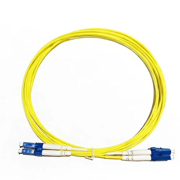
Align the fiber with the connector's guide. Ensure the fiber does not bend or twist during insertion. A proper fit prevents signal loss and enhances performance. Secure the connection using the fast connector's. Optical fiber fast connectors, also known as cold connectors, are becoming increasingly popular due to their ease of use and quick installation. Unlike traditional fiber connectors that require epoxy and polishing, fast connectors use a mechanical splice to join the fibers. In this article, we will. At the heart of any robust fiber optic network lies a crucial process: Preparing a fiber cable for termination of a connector or splice. Two types of splices are used in fiber optic cabling one is Mechanical the other is Fusion. Whether you're installing a new network, expanding an existing one, or. Optic Fiber cleaving, and mechanical splicing through very simple processes in this short series of videos. Thank you for supporting us by viewing our content. Doubts and suggestions? Leave us you. more Audio tracks for some languages were automatically generated. The primary purpose of a fast connector is to ensure a stable and reliable link. Connecting a fiber optic cable to a connector is a precise task that requires careful attention to detail, as well as some specialized tools and equipment. These terminations must be of the right style, installed in a.
[PDF]