This article provides a comprehensive guide on installing fiber optic patch panels, integrating practical installation steps with insights from business intelligence and data analytics. How to Install Fiber Optic Patch Panel Only by taking the proper steps can achieve a reliable network. For your convenience, the patch panel installation guide is divided into two sections. A successful project begins with careful planning. Whether you are a seasoned professional or new to the field, this guide is designed to enhance your understanding. ⚡ Level Up Your Fiber Skills – Join the One Up Techs Skool 👉 https://www. com/oneuptechs Please like, Subscribe, and comment any questions you may have. com/oneuptechs Most techs struggle because they: ❌ Don't. Keeping this page as a placeholder for now. What are the best practices for fiber patch panel installation? The best practices below help to avoid installation issues and ensure ease of service for the system. Penetrate the enclosure from the side or bottom to minimize the risk of water intrusion. Install grommets on all openings before. The fiber optical patch panel is convenient for people to easily access the optical fiber cable in the panel box, and can protect the optical fiber cable well. In addition, the drawer type structure is also conducive to high-density wiring and good cable management. However, because the optical.
[PDF]

This guide covers the critical steps, from selecting the right electrical cable tray and performing accurate cable fill calculations to managing a safe cable pull through and ensuring all bonding and grounding requirements are met. The purpose of this article is to define the sequence and methodology for the installation of electrical cable trays, cable trunking, cable raceways and boxes, junction and pull boxes. The method gives details of how the work will be carried out and what health and safety issues and controls that. The Cable Ladder & Tray Components – Assembly Guide presents a comprehensive visual walkthrough of the assembly and installation process for cable ladder and tray systems. The images meticulously detail each component involved, including ladder sections, cross-members, splices, and tray segments. Ladder style cable tray is a device used to support and protect wires and cables, commonly used in buildings, industries, and commercial places. The following are the installation steps for ladder style cable trays: 1. Preparation of tools and materials: The tools and materials required for the. Whether you're building a commercial setup or upgrading an industrial plant, proper cable tray installation ensures neat wiring, safe access, and easy maintenance. This guide breaks down the process step by step. Cable ladder systems and cable tray systems shall be manufactured in accordance with BS EN 61537, channel support.
[PDF]

Step-by-step instructions on how to install the Polylok 12" distribution or drainage box. In this guide, we'll break down everything you need to know to install a distribution box correctly and confidently. Choose the right box based on environment (indoor/outdoor), load capacity, and durability. Check for proper IP/NEMA ratings and material quality. Ensure safe placement: install in. Before starting the installation, finding a proper place for putting the distribution box is crucial, because it largely decides the safety and convenience of maintenance. Let's see what factors need to be taken care of when choosing the installation place. Accessibility is one of the most. Learn how to wire a distribution box step by step! This video shows real on-site footage of electrical installation, demonstrating safe and standardized wiring methods used by professionals. We'll simplify technical jargon, highlight common pitfalls, and equip you with actionable insights—because your safety and. To install one, you'll need to strip the ends off all the wires that will be in the box. To complete the electrical circuit, tie together the same-colored wires and hold them in place with wire nuts. Be sure to take the proper precautions so your home can be safely supplied with electricity for.
[PDF]

And fixed the frame on the front door position with 4 M5*8 self-tapping screws. 2, Use 16 M8*12 inner hex round screws and M8 flange nut for fixing the top & bottom panels into two side frames. 4, Insert back panel. Follow the instructions in this section to remove and install the side panels. Insert the key that comes with the rack cabinet into the key hole on the side panel, and turn it clockwise to unlock. If an IT cabinet is not equipped with side panels and placed in the end position, side panels need to be installed to ensure that the outer side of an end cabinet has side panels. Mark the mounting hole positions for the end cabinet based on the mounting holes in the cabinet side panel, and install. Complete Assembly Procesure for 9U Wall Mounted Network Cabinet (Single Section) How to assemble a wall-mounted network cabinet? 1, Insert top and bottom panel into the side frames. more How to assemble a wall-mounted. Installing and setting up a network cabinet system correctly is essential for maintaining an efficient and organized network infrastructure. In this comprehensive guide, we will walk you through the step-by-step process to ensure a successful installation and setup of your network cabinet system. Page 3 M3. 5 Attach Back Panel (H) to the rear of the cabinet frame,using M3. Click Side Panels (E) into place. To install the Tempered Glass Door (G), locate the side with two pins. Insert the fixed pin into door hinge hole. Pre – installation.
[PDF]

The detailed steps outlined herein provide a comprehensive understanding of optical attenuator installation and adjustment. Proper execution enhances the efficiency and stability of the attenuators and the overall communication system. Fibre optic attenuators, also called optical attenuators, are passive devices used to reduce the power level of an optical signal. Assemble all necessary tools and equipment, such as a fiber cleaver, fusion splicer, optical power meter, and connector cleaning tools. These are the cornerstones of a seamless installation. Equally. Having a deep understanding of how to select a fiber optic attenuator, regardless of the type—fixed or variable—and the type of fiber and connector is critical to the durability and maintainability of a reliable network. Taking optical power measurements before installation of a fiber optic. Optical Signal Attenuation is the single greatest factor limiting the distance and performance of your network. Understanding it is crucial for anyone involved in data centers, telecommunications, or enterprise networking. In this. 📦 For purchasing, use the RP Photonics Buyer's Guide for optical attenuators. It provides an expert-curated supplier directory, buyer-focused technical background information, and structured selection criteria to support professional procurement decisions. Optical attenuators are devices that.
[PDF]

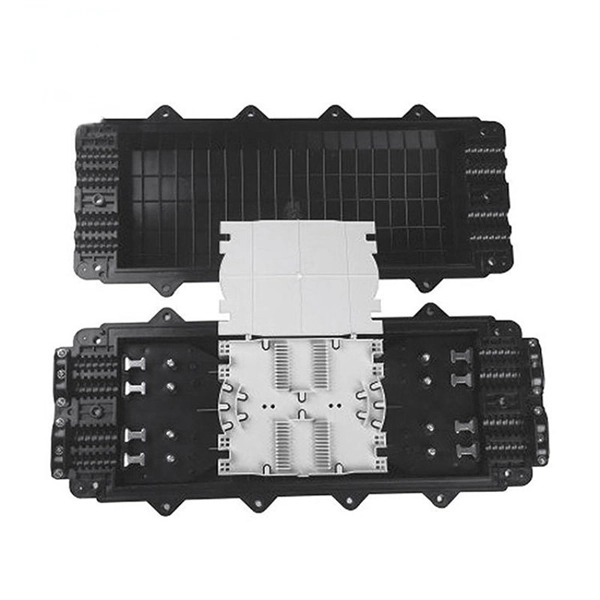
In this video, I walk you through my personal method of prepping and installing a 1:16 fiber optic splitter inside a sealed, weatherproof distribution box getting it ready for field deployment at a site. This is the way I've found to be clean, efficient, and reliable based on my experience in the. When employing the first-level splitting method in a residential network, optical splitters offer flexibility for indoor or outdoor installation. Indoor options encompass locations like the community's central computer room, building's weak current well, or floor wiring box. Optical cables can be. How to install the splitter distribution box is the important information we need to know. This article includes the following: 1. Install the fixture 2. Ground the installation system 1. Understanding Fiber Optic Splitter Box A fiber optic splitter box is a device used in fiber optic networks to split a single optical signal into multiple signals. This type of fiber optic cable splitter is generally placed in fiber splice closure or fiber splitter box. If plc splitter with connector, like bare splitter, mini plc splitter, there is a steel tube to protect the chip in the middle and the loose tube adhesion position. Have any questions? Talk with us directly using LiveChat.
[PDF]

The process involves a combination of national infrastructure, local engineering, and property-level setup. In this guide, we'll break down the fiber installation process from start to. This guide walks you through the complete fiber installation process, from checking availability to optimizing your Wi-Fi network performance. Fiber transmits data using light signals through glass strands, delivering faster speeds and lower latency than cable or DSL connections that rely on. In this article we'll break down how fiber internet is installed - from the network fiber drop outside your house to the in-home setup with your router and gateway - and what you should expect at each stage. Fiber optic internet is generally installed in the following 5 steps, which we'll dive. Want lightning-fast internet at home? Fiber optic installation is the way to go! It's super reliable and perfect for streaming, gaming, or using multiple devices. This guide breaks down the process in easy steps so you know what to expect. BCS Consultants, a trusted fiber optic installation company based in California, provides end-to-end fiber optic services, including expert planning. However, setting up a fiber optic connection to your router can seem daunting if you're unfamiliar with the process. In this guide, we'll walk you through how to connect a fiber optic cable to a router safely and efficiently. Why Use Fiber Optic Internet? Before diving into the setup, let's quickly.
[PDF]

See this topic to learn how to remove and install a door. Unlock and open the door. Removing a door Hold the door in place, and lift both hinge pins until they lock in the open position so that the door is disengaged. Remove the door from the rack cabinet frame. Install. Before installing your server in a rack cabinet, review the following guidelines: Two or more people are required to install the device in a rack cabinet. Ensure that the room air temperature is below 35°C (95°F). Do not block any air vents; usually 15 cm (6 in. ) of space provides proper airflow. In this comprehensive guide, we will walk you through the step-by-step process to ensure a successful installation and setup of your network cabinet system. Key steps include measuring the installation area, mounting rails, organizing cables, and testing stability. Proper grounding and compliance with safety. Page 3 M3. Click Side Panels (E) into place. To install the Tempered Glass Door (G), locate the side with two pins. With your thumb, pull down on the spring pin and slide it. Complete Assembly Procedure for 9U Wall Mounted Network Cabinet (Double Section) How to assemble a double section wall mounted network cabinet server rack? 1, Insert top and bottom panels into the side frames. And fixed the frame on the front door position with 4 M5*8 self-tapping screws.
[PDF]

Our guide delivers actionable, step-by-step best practices for rack layout, cable management, and patch panel installation. Following these steps helps you build a clean and efficient structured cabling system that simplifies maintenance and maximizes network performance. Patch panels are one of the best ways to manage an expansive local area network (LAN) by providing quick and easy access to the ports and connections that connect them altogether. Before a single cable is. H. Use cabinet screws to fix the network patch panel to the network cabinet. Note the wiring sequence on the patch panel when wiring, as T568A and T568B have different sequences. Different brands of patch panels may also have different wiring sequences, so always pay attention to the sequence. A patch panel is a board that houses multiple network ports. It acts as a bridge between incoming and outgoing Ethernet cables. Instead of plugging and unplugging devices directly from network switches, you connect them to the patch. Patch panels are a crucial component in any network infrastructure, providing a centralized location for managing cables and connections. By using patch panels, network administrators can simplify cable management, improve network scalability, and reduce downtime. This innovative tool combines precision with automation, ensuring accurate network documentation for IT professionals and network administrators.
[PDF]
Basic 300mm galvanized steel perforated trays can be found in the range of $1. 00 per meter, especially in bulk. Understanding the cable tray installation cost per meter is essential for effective budget planning. Costs vary based on tray material (steel, aluminum, or fiberglass), size, design (ladder or solid bottom), and installation complexity. Additional elements like supports, connectors, and brackets. Cable tray pricing depends on materials, coatings, size, supplier margins, and order quantity —plus hidden costs like shipping and installation. This guide breaks down everything buyers need to know, from price trends to cost-saving tips. The average cable tray price per meter ranges from $2 to. The majority of individuals will consider the cost of the components. But the actual price is the cash outlay to the workers to assemble the parts. Cable trays will tend to be significantly less expensive to use in 2026 than metal pipes due to their faster installation. 2 Why is Conduit So. Prices vary based on the size and load rating of the tray. For example: A standard 100mm wide GRP cable tray might cost around $15 per meter. Manufacturer and Brand Reputable brands often charge. The price for a 300mm width cable tray depends heavily on its type and material. We offer complete kits to provide you with cable tray ready to install under new or existing raised floors based on the unique requirements at your facility.
[PDF]
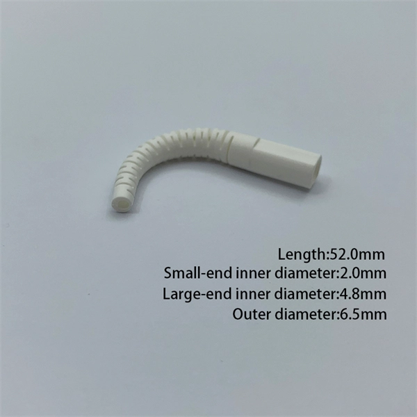
Many engineers don't know how to install this accessory. With the latest design, it can be confusing. So here is the instruction: 1. Determine the right height and the quantity of mounting bracket needed 2. Fix it on the gland. Distribution box installation How we make electrical enclosure more Easier DIY tool at home This DIY Woodworking Tool Changes Everything. If provided, proper installation of an equipment grounding terminal must be made and the rack must be grounded in accordance with NFPA 70, NEC, and the applicable sections of ANSI C2, “National Electrical Safety Code. " The equipment shall be installed by trained service personnel. All parts such as. Embarking on a Unistrut installation project can be both exciting and daunting. Whether you're venturing into medical support systems, ceiling grids, roof walks, or catwalks, ensuring a seamless installation requires careful planning and execution. In this guide, we'll delve into some expert tips. Whether you are an electrical contractor or a construction brigade, knowing how to properly and safely install distribution boxes is the basis of ensuring the safe operation of the entire system. This article details the process of installing them, which helps you comprehend distribution boxes. Before you buy electrical boxes, you want to be certain they have the right mounting holes for the devices you plan to install. Also be sure the boxes have correctly placed.
[PDF]
Lubricate your blade and cut following the angle of the circle impressions. Slide the seal into place from inside of the D-Box and tighten nut from the outside. Check to make sure you have completely tightened the nut and that the seal is not loose on the D-Box. How to install and utilize the pipe seals that come with the Polylok distribution boxes. Covers wiring, placement, standards, and expert tips for a compliant setup. A distribution box is the heart of any electrical system. It takes the incoming power and safely distributes it to different circuits throughout your building. more Polylok offers the only catch basin and distribution box seal on the market that accepts. Whether you are an electrical contractor or a construction brigade, knowing how to properly and safely install distribution boxes is the basis of ensuring the safe operation of the entire system. To open the seal tabs us a key or.
[PDF]

This video shows real on-site footage of electrical installation, demonstrating safe and standardized wiring methods used by professionals. You will learn to build a safe, efficient, and professional electrical system today. Circuit breaker wiring configurations involve organizing main switches, busbars, and branch breakers within a distribution box. Proper setups. An electrical panel box, also known as a breaker box or a distribution board, is a crucial component of any electrical system. It serves as a central hub for distributing electricity throughout a building, ensuring that power is delivered safely and efficiently to all the required locations. Choose the right box based on environment (indoor/outdoor), load capacity, and durability. Check for proper IP/NEMA ratings and material quality. And all the switching and protective devices are installed in the. Connection method: Each switch takes a wire from the incoming point and connects it to the incoming end of the switch, or uses parallel connection to reduce the difficulty of wiring. Wiring Direction: Wiring between the main circuit breaker and each branch circuit breaker in the box generally.
[PDF]