
This guide covers the critical steps, from selecting the right electrical cable tray and performing accurate cable fill calculations to managing a safe cable pull through and ensuring all bonding and grounding requirements are met. Article Summary: A compliant cable tray installation requires a thorough understanding of NEC Article 392, proper structural support, and precise installation techniques. But before you lay the first tray or clamp down a single cable, you need a solid plan. This guide breaks down the process step by step. This method statement describes a detailed procedure for properly installing cable trays and conduits for the Feeder System. It ensures that all installation activities follow authorized plans, specifications, and standards. The objective is to ensure safety, quality and compliance during the. Cable tray systems provide a safe, organized, and flexible method for supporting insulated conductors and cables in commercial and industrial electrical installations. Here is a step-by-step guide on how to install a standard metal cable tray system (e., ladder or perforated type). Before starting, ensure you have. en completely installed, without damage either to conductors or structural system use maintain spacing or to keep cables in place when the tray is ect the minimum bend ra-dius for cables as they exit the bottom of the cable tray. A rung spacing of 6 to 9 inches (150 to 230 mm) is preferable when.
[PDF]

In this short tutorial, I'll show you the tools, steps, and pro tips to fix wall boxes neatly for switches, sockets, and lights. Learn how to install a distribution box safely and correctly. Covers wiring, placement, standards, and expert tips for a compliant setup. It takes the incoming power and safely distributes it to different circuits throughout your building. It has three categories: residential, commercial and industrial electrical distribution boxes, all of which play important roles in their respective electrical. Standard procedures for lighting and socket installation provide safety, efficiency, and adherence to electrical codes. This post includes designing, wiring, mounting, testing, and safety inspections to guarantee that the electrical system operates properly and reliably. Material preparation: Prepare the required circuit breakers, wires, wiring ties and other materials, and ensure that they meet the design drawings and installation requirements. Perfect for beginners and electricians improving their skills. more Learn how to install electrical boxes. In modern electrical systems, cable distribution boxes (also known as electrical distribution boxes or distribution boxes) play a crucial role as the key hub for managing, distributing, and protecting circuits. Whether it is residential buildings, commercial facilities or industrial sites, the.
[PDF]
This guide will walk you through every step of the process, from selecting the right materials to securing connections and ensuring safety. Whether you're a seasoned professional or an enthusiastic DIYer, our detailed instructions will equip you with the knowledge and confidence to tackle this. Learn how to properly install an electrical box safely and efficiently. In this step-by-step tutorial, we'll cover: ✅ Tools you need. Covers wiring, placement, standards, and expert tips for a compliant setup. A distribution box is the heart of any electrical system. It takes the incoming power and safely distributes it to different circuits throughout your building. A neutral bar kit is a fundamental component within an electrical service panel, often called a breaker box, designed to manage the flow of electricity in a home or building. This metal strip serves as the termination point for all neutral conductors from the branch circuits. By consolidating these. Before starting the installation, finding a proper place for putting the distribution box is crucial, because it largely decides the safety and convenience of maintenance. Let's see what factors need to be taken care of when choosing the installation place. Beginning of dialog window. Escape will cancel and close the window.
[PDF]

Connect the phase and neutral wires from the input power supply to the input of the Main MCB. Learn how to install a distribution box safely and correctly. Covers wiring, placement, standards, and expert tips for a compliant setup. It takes the incoming power and safely distributes it to different circuits throughout your building. Learn how to wire a distribution box step by step! This video shows real on-site footage of electrical installation, demonstrating safe and standardized wiring methods used by professionals. Below is a quick checklist of everything you will need for a safe and efficient installation: Connecting a distribution box involves several steps to ensure proper electrical flow. It is usually equipped with circuit breakers, fuses, terminal connectors, and other components. It is mainly used to isolate fault circuits, prevent overload, and ensure the safe operation of. Box installation: Make sure that Distribution box has been correctly installed and fixed. Location determination:. An electrical panel box, also known as a breaker box or a distribution board, is a crucial component of any electrical system. It serves as a central hub for distributing electricity throughout a building, ensuring that power is delivered safely and efficiently to all the required locations.
[PDF]

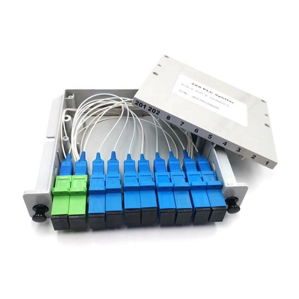
#FTTH #Fiber_to_the_Home* Watch this video to see how FTTH Fiber Optic Outdoor Distribution Box for Internet * FTTH Fiber Optic Outdoor Distribution Box இன்ஸ. A fiber termination box is the standard instrument used in fiber optic networks to connect, secure, and protect optical fibers at the terminating point. It functions as a junction between the incoming fiber cable and the outgoing customer-side fiber cable, where one fiber can be spliced, patched. The optical fiber distribution box allows people to easily access the optical fibers in the box, and can well protect the optical fibers. In addition, the drawer structure also facilitates high-density wiring and good cable management. However, because optical fibers are fragile and can be easily. Keeping this page as a placeholder for now. Have any questions? Talk with us directly using LiveChat. A fiber pigtail is a specific hardware connection used for cable termination. Thus, a fiber termination box is used to terminate the optical fiber. Using a fiber distribution box (FDB) enables the reliable transmission of data through fiber optic cables in networks small and large. As networks expand and more homes and businesses require high-speed connectivity, skillfully installing and managing an FDB becomes essential knowledge for any. A Fiber Termination Box, also known as a Fiber Distribution Box, is a crucial component in fiber optic networks. FTBs play a vital role in ensuring the.
[PDF]

This video shows real on-site footage of electrical installation, demonstrating safe and standardized wiring methods used by professionals. Let's break it down into two main parts: the outer shell and the electrical parts inside. The enclosure protects the electrical components from water, dust, and damage. When choosing one, check the IP or NEMA rating. A. The ideal location to install electrical distribution boxes should keep a distance from water, flammable and explosive substances and corrosive substances. If they need to be placed outdoors, especially in high humidity, you must ensure their waterproofness. Below is a quick checklist of everything you will need for a safe and efficient installation: Connecting a distribution box involves several steps to ensure proper electrical flow. Follow this guide. Box installation: Make sure that Distribution box has been correctly installed and fixed. Material preparation: Prepare the required circuit breakers, wires, wiring ties and other materials, and ensure that they meet the design drawings and installation requirements. Location determination:. Understanding the wiring diagram of an electrical panel box is essential for electricians and homeowners alike, as it allows them to troubleshoot any electrical issues, carry out repairs, or make additions to the system. The electrical panel box wiring diagram provides a visual representation of.
[PDF]
Step-by-step instructions on how to install the Polylok 12" distribution or drainage box. Covers wiring, placement, standards, and expert tips for a compliant setup. A distribution box is the heart of any electrical system. It takes the incoming power and safely distributes it to different circuits throughout your building. The installation of a distribution box is explored in detail, highlighting advanced techniques for achieving a professional and efficient setup. This video provides valuable insights for anyon. This article details the process of installing them, which helps you comprehend distribution boxes. Read and understand this entire manual and any additional site-specific installation documents before attempting to assemble, install, or operate the luminaire. If you have any questions regarding the product or installation, contact Cooper Lighting Customer Service at 1-800-573-3600. Wire strippers are essential when you install distribution box wiring.
[PDF]

This complete guide covers everything from identifying causes of failure to advanced repair techniques, drawing on the latest industry standards and innovations. A fiber termination box is the standard instrument used in fiber optic networks to connect, secure, and protect optical fibers at the terminating point. Proper installation and maintenance of FTBs are essential to ensure the reliability and performance of the network infrastructure. Before. By understanding these key elements and following the outlined steps, you can effectively repair fiber optic cables and maintain the high-performance network necessary for today's demanding communication needs. Whether you're a network technician, IT professional, or telecom operator, you'll find practical steps, tools, and tips to restore. FTTP or fiber To The Premises applications have reinforced the importance of reliable and stable fiber optic terminations. Good quality fiber laying and termination systems help achieve minimal back reflection and low signal loss. They also feature resistance to moisture, impact, chemical exposure. A fiber optic distribution box, also known as a fiber optic terminal box or fiber optic termination box, is a device used to connect and manage fiber optic cables in a network. The distribution box provides.
[PDF]

First, connect each pre-terminated fiber optic cable to the adapter panel separately, making sure the ports correspond one-to-one; then fix the fiber optic adapter panel to the front panel of the distribution box with the bend radius control clip. In general, installing the optical fiber distribution box can be divided into three steps: installing the optical fiber distribution box on the rack, introducing the optical cable into the optical fiber distribution box, and planning the optical fiber path in the optical fiber distribution box. The. Bottom installation: Select a proper installation position in the equipment room and drill four holes in the floor according to the dimensions shown in the manual. Fix the rack to the ground with expansion bolts. Top installation: Dimensions of four connection holes on the top according to the. The Optical Distribution Box (ODB) is high-density 2-in-2-out fiber box solution. Designing with a compact size of 340x220x100mm, the cabinet accommodates 1x2,1x4,1x8 and 1x16 etc. The 4 ports are sized for main cable from 9 to 16mm in diameter, along with 16 3mm cables. Accessory Kits:. Install the optical fiber distribution box on the rack. Ensure that the box is installed firmly and horizontally, and the deviation of perpendicularity is not greater than 3mm.
[PDF]

This video shows real on-site footage of electrical installation, demonstrating safe and standardized wiring methods used by professionals. The National Electrical Code (NEC) Section 700. 10 provides critical guidelines for the wiring of emergency systems. These systems ensure continued operation during power outages, protecting lives and maintaining functionality in key buildings. This guide breaks down the essential requirements of. Emergency system circuits supply power to critical life safety loads such as emergency lighting, fire alarm systems, fire pumps, smoke control systems, and essential communication and control circuits. Correct wiring design for emergency system circuits is essential to maintain power integrity. The general rule in 700. 10 (B) is to keep wiring from an emergency source or emergency source distribution overcurrent device to the emergency loads entirely separate from all other wiring and equipment, unless otherwise permitted in 700. 10 (B) (1) through (5). 12) of the interruption of the normal electrical supply.
[PDF]

In this video, we'll walk you through the process of wiring a home distribution box with a detailed connection diagram. Whether you're an electrician or a DIY enthusiast, this guide will help you understand the basics of home electrical distribution. more Welcome to our channel! In this video. This guide provides step-by-step instructions for connecting a distribution box and highlights key factors to consider during installation. What Is a Distribution Box? A distribution box, also known as an electrical distribution board, is a critical component in electrical systems. It has three categories: residential, commercial and industrial electrical distribution boxes, all of which play important roles in their respective electrical. Understanding how to safely set up the main connections of a home's power distribution system is essential for ensuring reliable and secure operation. A correct installation process minimizes the risk of electrical faults and increases the longevity of your setup. It is usually equipped with circuit breakers, fuses, terminal connectors, and other components. It serves as a central hub for distributing electricity throughout a building, ensuring that power is delivered safely and efficiently to all the required locations.
[PDF]
The aluminium alloy joint box are applicable for connection protection of special optical cables,with the functions of direct and branch connection, with the maximum of 6 optical cables, which mainly for overhead rods and towers. Explore top-quality OPGW hardware fittings, setting a new standard for secure and efficient connections in our Pole Line Hardware. The joint box is made of aluminium alloy and has a maximum capacity of 192 fibre splices. A pre-moulded neoprene anti-aging gasket. No. 77, East District, Sixian Industrial Zone, West Ring Road Office, Renqiu City,. An assembling plate trays is placed inside the box. Cable glands and a heavy wall OPGW cables. The anchoring of the joint box to the tower is poles. It features in high mechanical strength, good airtight and anti-corrosive. Having been sealed with sealing ring and silicone, it could be opened, expansed, fixed, and connected repeatedly. It's suitable in aerial. Optical cable junction boxes play a crucial role in connecting and protecting optical fibers, directly influencing the quality and lifespan of optical cable routes. Optical cable splice boxes protect the splicing parts of optical fibers from various hazards, such as water seepage due to adverse.
[PDF]

This guide summarizes field-proven rules for AI/AO/DI/DO wiring, shows how to choose between NO/NC contacts under the fail-safe principle, and explains how to decode typical cable schedule entries. Instrument installation with the associated cable installation/electrical signal and control wiring should be carried out by skilled personnel who are acquainted with the safety requirements and regulations for the plant site for that specific project. Generally instrument cabling is usually run in. Few factors are to be considered or taken care of while wiring a field instrument to control panel. Based on noise susceptibility limits (NSL) according to IEEE 815 standard, various field instrument signals are classified as below. Noise Susceptibility Limit Grounding of the signal cable Type of cable Cable Terminations Based on noise susceptibility limits (NSL). Note how the hoop-shaped “jumper” wires are all cut to (nearly) the same length, and how each of the wire labels is oriented such that the printing is easy to read: This next photograph shows a great way to terminate multi-conductor signal cable to terminal blocks. Each of the pairs was twisted. A well-designed and properly installed instrument junction box is crucial for the efficient operation and maintenance of electrical systems. Level 1: High to medium susceptibility Level 2: Low susceptibility.
[PDF]
