
See this topic to learn how to remove and install a door. Unlock and open the door. Removing a door Hold the door in place, and lift both hinge pins until they lock in the open position so that the door is disengaged. Remove the door from the rack cabinet frame. Install. Before installing your server in a rack cabinet, review the following guidelines: Two or more people are required to install the device in a rack cabinet. Ensure that the room air temperature is below 35°C (95°F). Do not block any air vents; usually 15 cm (6 in. ) of space provides proper airflow. In this comprehensive guide, we will walk you through the step-by-step process to ensure a successful installation and setup of your network cabinet system. Key steps include measuring the installation area, mounting rails, organizing cables, and testing stability. Proper grounding and compliance with safety. Page 3 M3. Click Side Panels (E) into place. To install the Tempered Glass Door (G), locate the side with two pins. With your thumb, pull down on the spring pin and slide it. Complete Assembly Procedure for 9U Wall Mounted Network Cabinet (Double Section) How to assemble a double section wall mounted network cabinet server rack? 1, Insert top and bottom panels into the side frames. And fixed the frame on the front door position with 4 M5*8 self-tapping screws.
[PDF]

The mounting height of a network rack typically ranges from 24 inches to 84 inches (2 to 7 feet), depending on the equipment and installation requirements. A server rack is more than just a physical frame—it determines how well your rack servers, network switches, PDUs, and storage arrays can be organized, cooled, and maintained. Selecting the right rack size ensures not only compatibility with today's hardware but also room for future expansion. The. Common server rack sizes are 19‑inch width, heights like 42U or 48U, and depths from ~24″ to 48″. Choose size based on equipment type, cooling, space, and future growth. Most IT environments default to 42U, 19-inch width, and 1000–1200 mm depth unless space constraints or special equipment dictate. A rack unit, abbreviated as “U,” is the standard unit of measurement for the height of devices designed for rack mounting. One rack unit equals 1. Important: U describes height only, but a server's real "capabilities" are also determined by chassis depth, internal layout, airflow, rails, power, and expansion (PCIe/risers, NVMe. You'll get precise, vendor-agnostic dimensions for standard server rack sizes—including exact width (19″ internal / 24″ external), height (42U = 73. 5″), depth (24″–48″), and the universal 1U = 1. 75″ rule—plus how to verify usable space, avoid common fitment errors, and select based on equipment.
[PDF]

The system cover is off or incorrectly installed. The intrusion switch might be triggered or not working. In this scenario at least one fan or fan assembly (contains two fans) is either damaged (connector, fan blade, fan blade frame), missing or failed. Check the front LCD or system event log to. What do the BMC logs say? Does the server overheat? Are the fans just off because it's not under load? what kind of server do you have, give a spec sheet. Server fans maintain critical airflow to prevent component overheating and system failures. (Adapted from hardware diagnostic methodologies in service docs) 💡 *Pro Tip: Replacing bearings extends fan life by 2-3 years at 20% of new fan cost* (Cost data from “Dell & HPE Server Repair Services. we've got 3 Dell PowerEdge R6615 with an AMD Epyc 9174F in it and the fans are doing something weird. Most of the time they are at 8-9k RPM and fairly quiet. But every minute or 2 they are revving up to full speed (~ 24k) or half speed (~ 13k) and then back down. From failed capacitors to deep grime hiding in your rotor shaft — I show you how to diagnose each fault step-by-step using. Server racks can get hot fast. When the heat isn't managed well, it can slow down your servers, cause shutdowns, or even damage your equipment. Over time, this.
[PDF]

Long Expansion Cycle: Optical fiber preform production has high technological barriers, and the expansion cycle can take as long as 18-24 months. Even if manufacturers start expanding immediately, the new capacity will not be available until at least 2027. This phenomenon is the result of multiple factors, including tight supply of optical fiber preforms (preforms), long expansion cycles for optical fiber production capacity, and the explosive growth of emerging applications such as AI computing power and drones. The expansion cycle of optical fibers is generally less than 6 months, and fiber optic cables can take 3 months. The expansion of production requires the purchase of equipment and the construction of factories. At the heart of this transformation lies fiber optic cable manufacturing, a precise and sophisticated process that powers our interconnected world. With the global fiber optic market reaching $6 billion and growing at 10% annually, the need for high-quality manufacturing solutions has never been. The manufacturing process of fiber optic cables involves several intricate steps that culminate in the production of high-performance data transmission solutions. This process begins with the creation of a preform, which serves as the foundation for the optical fibers within the cable. This intricate process combines cutting-edge technology, precise engineering, and.
[PDF]
It is relatively affordable, especially when considering its durability and long lifespan. Additionally, it requires minimal maintenance, reducing ongoing costs. It is generally easy to install and can be quickly integrated into different systems or structures. Cable Tray is often a cost-effective solution compared to other materials. However, since this design is open, it. Cable tray pricing depends on materials, coatings, size, supplier margins, and order quantity —plus hidden costs like shipping and installation. This guide breaks down everything buyers need to know, from price trends to cost-saving tips. Additionally, these solutions help ensure compliance with fire safety codes and regulations, fostering a safer environment. Ensure your infrastructure's safety with NewReach Fire Rated. Lightweight: GRP cable trays are significantly lighter than metal cable trays. Electrical Insulation: GRP cable trays provide excellent electrical insulation. The landscape is shaped by regional manufacturing dominance and evolving buyer preferences. The market is growing steadily, driven.
[PDF]

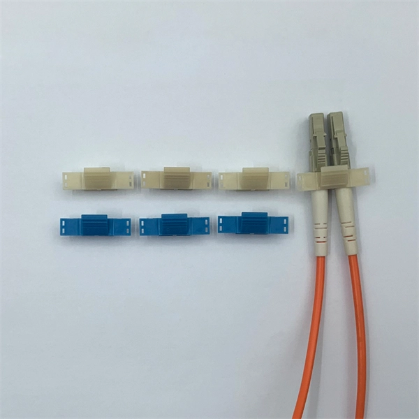
Optical couplers can split or join signals in fibers. You can connect many users to one port with 1:n or 2:n splitters. These devices work both ways, which helps strong network communication. They help send. This small device connects or joins optical fibers together. It helps networks grow and change when needed. Learn about the two main types of fiber optic couplers: fused and planar. Fused. How to Choose the Right Fiber Coupler (FTTH, Data Center & More) Are you in the process of designing a Fiber to the Home (FTTH) network, but wondering how to split one fiber for multiple users? Or maybe you are operating a data center, and you would like to use a single signal to provide to. Fiber optic couplers are optical devices that connect three or more fiber ends, dividing one input between two or more outputs, or combining two or more inputs into one output. The device allows the transmission of light waves through multiple paths. Fiber optic couplers can either be passive or. A fiber optic coupler is a passive optical component that splits, combines, taps, or redistributes light between optical fibers. In real-world networks, couplers let one signal reach many users, allow several signals to share one fiber path, or sample a small amount of light for monitoring. 5/125 µm fiber, with low insertion loss and a broad operating wavelength range from 800 to 1600 nm. The 1x2 and 2x2.
[PDF]

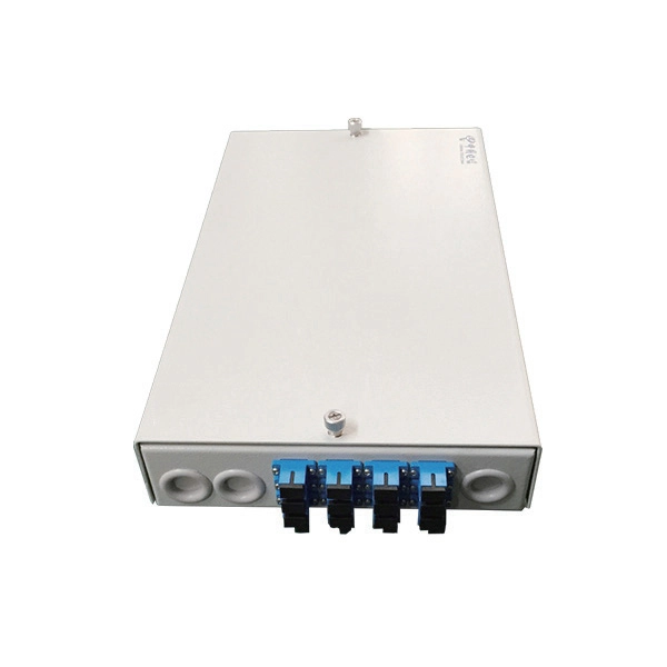
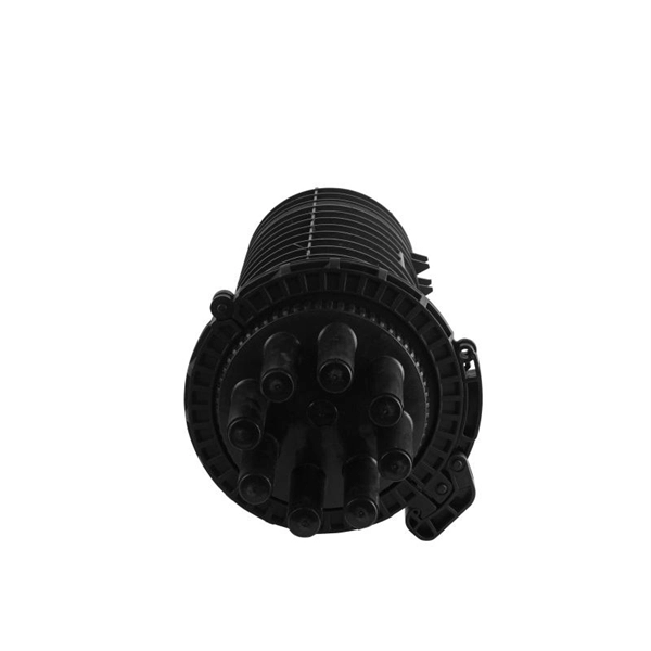
In this step-by-step tutorial, learn how to splice fiber optic cables like a pro — perfect for telecom technicians, network engineers, and field techs. more 🔧 Watch a real-time fiber optic splicing demo in action!. Fiber cable splicing is a critical step in building reliable fiber optic networks. Whether in data centers, telecom rooms, or outdoor FTTx deployments, proper splicing inside a fiber enclosure ensures low signal loss, long-term stability, and easy maintenance. This guide explains what fiber cable. In this guide, we cover the basics of fiber optic splicing, how to perform splicing using two different methods, and finally some best practices to perform good fiber splicing. What is Fiber Optic Splicing and Why is it Needed? – #1. Whether repairing a broken cable or extending a fiber run, fiber optic splicing ensures light signals travel. Regardless of your level of experience, creating high-quality, high-performance fiber optic networks requires developing your skills in fusion splicing. This guide reveals the secrets to fusion splicing with little fluff—just proven, straightforward techniques refined from years of work in the.
[PDF]

This guide walks you through the complete fiber installation process, from checking availability to optimizing your Wi-Fi network performance. Upgrading to fibre internet involves replacing your existing copper cables with new fibre-optic ones. This upgrade brings faster speeds and more reliable connectivity. Here is what the installation process is like: One of our technicians will visit your home, remove the old copper wiring and. If you need Fiber Optic Cable Installation in Malta or areas close by allow us to assist you by connecting you with specialized pros who can do the work you request. Step 1: Planning Before any installation begins, thorough planning is essential. This includes determining the network's requirements, such as bandwidth, distance, and the number of. This guide will explain the entire set of activities involved in installing Fiber optic cable contractors -from the early planning stage right through testing-for facility managers, IT teams, and low-voltage contractors to build high-performance networks safely and efficiently. The processes. The Fiber Optic Association, Inc. (FOA) was founded in 1995 to help develop the workforce to build the fiber optic networks to support a rapid expansion in communications and the Internet. The charter of the FOA was to promote professionalism in fiber optics through education, certification, and. We offer :- For more information email us on sales@merlin.
[PDF]

When it comes to testing fiber optic cables, a Visual Fault Locator (VFL) is an essential tool in your toolkit. A VFL is used to detect faults, breaks, or bends in fiber optic cables by emitting a bright red light that is visible even through the fiber's jacket. It's a cost-effective and. A Visual Fault Locator which can be also called visual fault identifier (VFI), fiber fault locator, fiber fault detector, etc., is a visible red laser light designed to inject visible red light energy into an optical fiber. Using a VFL to diagnose issues can save time and cost when diagnosing an. A visual fault locator is a compact, handheld device that emits a visible light beam, typically in the red wavelength range, through a fiber optic cable. It works by injecting a visible red laser light into the fiber, which can be seen through the jacket or at the end of the cable. If the light doesn't come out the other side, there might be a problem. You. And in the end we will show you how to use an old cell phone's camera to detect light in a fiber optic system. It uses a bright incandescent bulb or visible LED source to.
[PDF]
This article delves into the intricate steps of busbar selection, preparation, and installation, ensuring efficient and safe power distribution. You'll discover the essential tools and techniques. FlexLine® busbars PSX go hand in hand with the flex terminals of the FlexLine® protection devices by following an one-size-fits-all approach. Whenever the neutral conductor terminals are not required, the flex terminals accommodate this busbar pin without any mechanical or electrical connection. BEIENE Smart 3 in 1 Busbar Processing machine is with our Intelligent 3D Busbar Program software Smartnest. From 3D Drawings, your busbar can be processed directly. Also can be optimized the production by the nesting function !. more BEIENE Smart 3 in 1 Busbar Processing machine is with our. 40 mm bar centre distance, 3-pole, space-saving plug-and-lock connection from the front, support suitable for top-mounting, all-round contact hazard protection. Our Mother company was founded in 1955 which is the Top Hydraulic research and developing institute in China! “Say Goodbye to CNC Machine, Open your Intelligent Times” this is our commitment to each customer !.
[PDF]
This integration is achieved through the use of wavelength division multiplexing (WDM) filters, which separate the transmit and receive wavelengths within the same fiber. These modules play a vital role in transmitting and receiving optical signals. TOSA ( Transmitter Optical Sub-Assembly), converts electrical signals into optical signals for transmission. In this mode, the WDM system transmits multi-wavelength optical signals in receive and transmit directions through separate fibers. Simple design and low requirements. If you're dealing with data centers, telecommunications, or AI networking, grasping the key parameters of an optical. In the era of 5G, AI, and high-speed data centers, optical modules serve as the core bridge for converting electrical signals to optical signals (and vice versa), enabling fast, reliable data transmission across networks. Among various optical module form factors, SFP (Small Form-Factor Pluggable). Fiber optic transceivers are key components of the fiber optic transmission network. They are designed in small form-factor with some integrated optical sub-assemblies which can be suitable for the high-density network. There are many SFPs available in the market with different features and. Most systems operate by transmitting in one direction on one fiber and in the reverse direction on another fiber for full duplex operation.
[PDF]

Get access to all 80 remaining Manufacturers with complete contact information, addresses, and business details. As of January, 2026, we have compiled data on 90. CHEC Guyana Incorporated. LEXICON HOLDINGS INC. QINGJIAN GROUP COMPANY (GUYANA) INC. Orange Light – BSO INC. Global Stars International Imports & Exports. Imperial Radiator Services Limited. Visit the post for more. Find 86 Manufacturers & Suppliers in the Guyana. You can also list your company here for free. Vegetables And Other Local Products. Here are the top-ranked cable rack companies as of April, 2026: 1. Marken Manufacturing, Inc, 2. Osburn Associates, Inc. What Is a Cable Rack? Engaged in research on nitride semiconductor. There are 90 Manufacturers in Guyana as of December, 2025. **** Fibre-Tech Industria. **** Massy Gas Products G. ****. Guyana is a sovereign state on the northern mainland of South America. It is, however, included in the Caribbean Region due to its strong cultural, historical, and political ties with the Caribbean Community (CARICOM). With $990M in revenue, Guyana Sugar is ranked first on the list, followed by National Hardware with $35. Find additional information about some of the biggest.
[PDF]

The process involves a combination of national infrastructure, local engineering, and property-level setup. In this guide, we'll break down the fiber installation process from start to. This guide walks you through the complete fiber installation process, from checking availability to optimizing your Wi-Fi network performance. Fiber transmits data using light signals through glass strands, delivering faster speeds and lower latency than cable or DSL connections that rely on. In this article we'll break down how fiber internet is installed - from the network fiber drop outside your house to the in-home setup with your router and gateway - and what you should expect at each stage. Fiber optic internet is generally installed in the following 5 steps, which we'll dive. Want lightning-fast internet at home? Fiber optic installation is the way to go! It's super reliable and perfect for streaming, gaming, or using multiple devices. This guide breaks down the process in easy steps so you know what to expect. BCS Consultants, a trusted fiber optic installation company based in California, provides end-to-end fiber optic services, including expert planning. However, setting up a fiber optic connection to your router can seem daunting if you're unfamiliar with the process. In this guide, we'll walk you through how to connect a fiber optic cable to a router safely and efficiently. Why Use Fiber Optic Internet? Before diving into the setup, let's quickly.
[PDF]