This guide will walk you through every step of the process, from selecting the right materials to securing connections and ensuring safety. Whether you're a seasoned professional or an enthusiastic DIYer, our detailed instructions will equip you with the knowledge and confidence to tackle this. Learn how to properly install an electrical box safely and efficiently. In this step-by-step tutorial, we'll cover: ✅ Tools you need. Covers wiring, placement, standards, and expert tips for a compliant setup. A distribution box is the heart of any electrical system. It takes the incoming power and safely distributes it to different circuits throughout your building. A neutral bar kit is a fundamental component within an electrical service panel, often called a breaker box, designed to manage the flow of electricity in a home or building. This metal strip serves as the termination point for all neutral conductors from the branch circuits. By consolidating these. Before starting the installation, finding a proper place for putting the distribution box is crucial, because it largely decides the safety and convenience of maintenance. Let's see what factors need to be taken care of when choosing the installation place. Beginning of dialog window. Escape will cancel and close the window.
[PDF]

Pictures and step-by-step instruction for splicing household electrical wiring to extend a circuit. Connecting wires to your home distribution box? See how electricians do it professionally! From selecting the right wire gauge to safely connecting the main. A distribution board or distribution box is where the main power supply is distributed to multiple loads. And all the switching and protective devices are installed in the distribution box. Single Phase Distribution Box generally consists of Double Pole MCBs, Single Pole MCBs, and RCCBs. Covers wiring, placement, standards, and expert tips for a compliant setup. It takes the incoming power and safely distributes it to different circuits throughout your building. Whether you're an electrician or a DIY enthusiast, this guide will help you understand the basics of home electrical distribution. What is Distribution Board? Distribution board. Always begin with disconnecting the main supply before accessing any enclosure containing distribution components. This prevents arc faults and ensures safety when modifying or inspecting current paths. Inside the service housing, line conductors from the utility feed typically enter through the. A plastic connector, called a wire nut, is used to insulate and secure the splice. Wire splice connections must be housed inside a covered electrical box, known as a junction box. A junction box is usually square.
[PDF]

Dubai Electricity and Water Authority (DEWA) extended over 364 kilometres of Fibre Optic (FO) ducts across different areas in Dubai in 2023. This has increased the total length of these cable ducts to 3,998 kilometres, a 10% increase compared to 2022. Fibre refers to a type of internet connectivity where information is transmitted via fibre optic cables. This is in line with DEWA's efforts to build a. As w. media's Global Editor-in-Chief, Grey covers the cloud and data center industry and connectivity ecosystem across APAC and EMEA. In a career spanning over two decades, Grey has dabbled in television, print and online journalism, covering a variety of beats including human rights, health. Please try refreshing the page. Visualize the growth of global connectivity. Flexible No Contract Option At AED 2250 / Month Best fiber internet deals in Dubai: du's cable plans deliver 250Mbps to 1Gbps. Includes free smart router and 24/7 premium support. We do have Etisalat approved and DU approved brands in Fiber optic brand with us. We keep complete Stock Fiber Optic Products from 2 Core FTTH cables to 48Core cables in Single mode and Multimode ( OM2, OM3 and OM4).
[PDF]

This article will give you an overview of the use cases for fiber-optic networking, some of the terms used in fiber networking, and suggestions for setting up a fiber network. Once you understand the basic concepts, you can check out my Recommended Equipment section toward. Fiber tapping is a network tap method that extracts signal from an optical fiber without breaking the connection. Tapping of optical fiber entails diverting some of the signal being transmitted in the core of the fiber into another fiber or a detector. Fiber to the home (FTTH) systems use beam. Optical fiber is a technology used to transmit data by sending short light pulses along a long fiber, which is typically made of glass or plastic. In optical fiber communication, metal wires are preferred for transmission because the signals travel more safely. Optical fibers are also resistant to. Photo: Light pipe: fiber optics means sending light beams down thin strands of plastic or glass by making them bounce repeatedly off the walls. This is a simulated image. Note that in some countries, including the UK, fiber optics is spelled "fibre optics. " If you're looking for information online. This manual covers everything about fiber optic cables, how they work, where they are used, and what is new in this area of technology. The choice of fiber optic cable depends on the specific needs of the application, as well as the.
[PDF]

The good news is that network cabinet prices range from as low as $100 for basic wall-mounted units to over $3,000 for specialized outdoor models. However, understanding what drives these costs will help you make a smart buying decision. In this complete guide, we'll break down everything you need. Check each product page for other buying options. VEVOR 6U Wall Mount Network Server Cabinet, 15. 5" Deep, Server Rack Cabinet Enclosure, 200 lbs Max. 5". Explore our top-tier selection of Networking Cabinets and Racks designed to keep your IT infrastructure organized and secure. Whether you're setting up a home lab, a corporate data center, or managing network equipment for a small business, our collection offers robust and versatile solutions. Cabinets are used for storing routers, patch panels, switches and a wide variety of networking equipment and accessories. Network cabinets support large, modular network switches by providing additional space for cable management and. Network cabinets are enclosed systems designed to securely store, organize, and protect networking and IT equipment such as switches, routers, patch panels, servers, power strips, and cable management components. They allow users to secure their data and communication connections. The product will be reserved for you when.
[PDF]

As a key parameter for evaluating data transmission accuracy, the bit error rate directly determines the reliability and stability of communication systems. This article delves into the fundamentals and testing methods of the bit error rate. A bit error occurs when a single binary digit is flipped during transmission, meaning a logical '0' is mistakenly interpreted as a '1' by the receiver, or a '1' is read as a '0'. Through the interpretation of actual test reports, it. BER is calculated by comparing the transmitted sequence of bits to the received bits and then counting the number of errors. The ratio of how many bits received in error over the total number of bits received is the BER. This ratio is affected by many factors including: signal to noise, distortion. Bit Error Rate (BER) is a crucial metric in signal processing and communication systems, measuring the frequency of errors in data transmission. It is defined as the ratio of the number of bits received in error to the total number of bits transmitted over a communication channel during a specified. In the fast-paced world of digital communication—where billions of bits travel through wires, fibres and wireless links every second—the concept of bit error rate (BER) is both fundamental and profound. It involves measuring the rate at which errors occur in a transmitted bitstream compared to the expected bitstream at the receiver end. The BER measurement helps in assessing the quality.
[PDF]

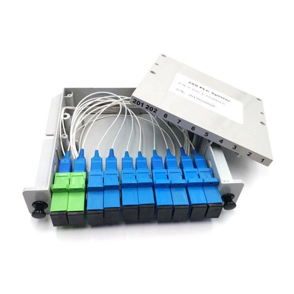
Insertion loss tells you how much weaker the signal becomes after passing through the splitter. Let's say you have a laser output at 0 dBm (which is 1 milliwatt of optical power). If you use a 1×8 splitter with ~10. 5 dB of insertion loss, the power at each output would be: 0 dBm – 10. 5. Enter excess loss from the splitter datasheet for your wavelength. Add connector and splice quantities with realistic planning losses. Include any additional component losses and an engineering margin. Enable power budget to estimate received power and margin. Press Calculate to show results above. Understanding optical splitter loss isn't just about plugging numbers into a calculator. It's about knowing what factors contribute to that loss, how manufacturers specify it, and how it impacts the overall performance and reach of your network. Ignore it, and you might find your signal too weak to. Optical insertion loss refers to the signal loss resulting from the insertion of components such as connectors or splices in an optical fiber system. Common ratios: For cascades, add losses and validate margin using the Optical Budget tool. This Fiber Optic Splitter Insertion Loss is the splitter devices loss, Considering fiber connectors or connectors+adapter insertion loss in LGX, The fiber splitter IL would be a little bigger. To make clear the basic ftth fiber splitter loss in performance, You can refer to the below loss chart.
[PDF]

On average, you can rent a Fusion Splicer for $275/day, $773/week, $1424/month. The price of these splicers can be higher because of their mechanical complexity and ability to handle various fiber types, including large-core fibers. Hybrid splicers bring in various features that are present in both automatic splicers and manual splicers. They can be aligned by the core. Fiber optic fusion splicers are critical tools for deploying and maintaining fiber networks, with significant variations in performance, features, and pricing. This guide breaks down the key cost-influencing factors across five dimensions—splicer types, technology, performance, accessories, and. A fiber optic splicing machine is a specialized machine used to fuse two optical fibers together to form one long one. The machine, also known as a fiber optic fusion splicer, uses electricity to melt the two optic cables into one. The fiber fusion splicer conducts the fusion with high accuracy to. Check each product page for other buying options. Get reliable equipment with fast splicing times and comprehensive accessories included. It features a mini handheld design, integrated buttons and touch screen, simple operation, low.
[PDF]

When switching to fiber internet, many users wonder if they're able to use their own router instead of the one provided by their internet service provider (ISP). In this guide, we'll explain router compatibility, setup steps and whether upgrading your router is necessary to maximize fiber speeds. Selecting a single router can be challenging, as there are most likely many that fit the requirements you want. We've done the research for you and put together this in-depth guide that lists multiple options, their details, reviews, and pros and cons. This should help you make an informed decision. Unlike cable internet, fiber connections do not require a cable modem. Instead, you simply plug a wireless router into the ONT provided by your ISP, set it up, and start using the internet. But if you're unsure which router to get, you're in the right place. Instead of using your old router, a high-performance Wi-Fi router designed for fiber optic internet will ensure you seamless streaming, online gaming, and remote work all. This article provides a comprehensive review and buying guide designed to assist in identifying the best routers for fiber internet. We will explore key performance metrics, essential features such as Wi-Fi standards and port configurations, and examine a range of router models optimized for fiber. Yes, you can often use your existing router with fiber optic internet, but there are crucial considerations. This guide will break down everything you.
[PDF]

The Optical Time Domain Reflectometer (OTDR) is useful for testing the integrity of fiber optic cables. It can verify splice loss, measure length and find faults. The OTDR is also commonly used to create a "picture" of fiber optic cable when it is newly installed. The Contractor tasked to perform testing or splicing on any fiber optic cable will follow these testing standards to fulfill their contractual obligations. The Contractor must utilize the correct equipment and testing techniques to gain acceptance, or the work cannot be approved. Later, comparisons can be made. For every fiber optic cable plant, you will need to test for continuity, end-to-end loss and then troubleshoot the problems. If it's a long outside plant cable with intermediate splices, you will probably want to verify the individual splices with an OTDR also, since that's the only way to make. ic system. Fiber optic testing of a newly installed system not only verifies that the system meets its design requirements, but also creates a performance baseline for all future testing and troubleshooting of t at system. What is Fiber Optic Splicing and Why is it Needed? – #1. Use and Maintain Your. This guide reveals the secrets to fusion splicing with little fluff—just proven, straightforward techniques refined from years of work in the field. The guide provides the complete workflow, covering safety precautions, tool selection, fiber preparation, fusion operation, quality control, and.
[PDF]

These screws should be 1 to 1. 5 inches long to penetrate the box and embed into the center of the stud without protruding out the back. When attaching boxes to metal studs, the preferred fastener is a self-tapping or self-drilling metal screw, such as a #6 or #8 size with a pan or. These screws should be 1 to 1. All sorts of grounded electrical metal things are mounted with self-drilling or self tapping screws that do not have 32 threads. Leviton Comment: We are covering Articles 312. 10 Screws or Other Fasteners. Screws or other fasteners installed in the field. The length of the device screw varies based on the box depth and its recess from the finished wall surface. Standard installations often use screws between 1/2 inch and 3/4 inch long, but deeper boxes or those requiring adjustment spacers may necessitate screws up to 2 inches. Using a machine screw. These standard metal boxes have been secured by driving self-tapping screws through the 1/8-inch diameter mounting holes in the side of the box and into the horizontal metal stud. Code Change Summary: Changes were made to the. My plan to ground the outlet is to use a self-tapping metal screw fixed to the back of the box. Is this a proper method of connecting the outlet ground. The old boxes have tiny threaded holes at the front of the box, but they are too small for a standard machined ground screw. The threads are a 10/32" size thread. The 4020513001K.
[PDF]

Connect the phase and neutral wires from the input power supply to the input of the Main MCB. Learn how to install a distribution box safely and correctly. Covers wiring, placement, standards, and expert tips for a compliant setup. It takes the incoming power and safely distributes it to different circuits throughout your building. Learn how to wire a distribution box step by step! This video shows real on-site footage of electrical installation, demonstrating safe and standardized wiring methods used by professionals. Below is a quick checklist of everything you will need for a safe and efficient installation: Connecting a distribution box involves several steps to ensure proper electrical flow. It is usually equipped with circuit breakers, fuses, terminal connectors, and other components. It is mainly used to isolate fault circuits, prevent overload, and ensure the safe operation of. Box installation: Make sure that Distribution box has been correctly installed and fixed. Location determination:. An electrical panel box, also known as a breaker box or a distribution board, is a crucial component of any electrical system. It serves as a central hub for distributing electricity throughout a building, ensuring that power is delivered safely and efficiently to all the required locations.
[PDF]
Picking up the best router for fiber internet isn't just about going to the market and choosing one of the best wireless routers. Instead, you need to carefully look at its specs, performance, and the type of securit.
[PDF]
