
For busbar sizing, the primary references are IEC 61439 (for low-voltage switchgear and controlgear assemblies) and IEC 60287 (for current-carrying capacity of cables). IEC 61439 is a standard developed by the International Electrotechnical Commission (IEC) that covers design verification for low-voltage electrical products and assemblies. The IEC 61439. With SIRIUS, SENTRON, SIVACON and ALPHA, we offer an innovative portfolio for standard-compliant and demand-oriented applications. Efficient engineering tools and innovative cloud-based solutions can be flexibly tailored to individual requirements. com/system-certificates/ep). The. 7 cycles of 24 h each to salt mist test according to IEC 60068-2-11; (Test Ka: Salt mist), at a temperature of (35 ± 2) °C. The test shall be carried out according to IEC 60068-2-2 Test Bb, at a temperature of 70 °C, with natural air circulation, for a duration of 168 h (7 days) and with a recovery. The International Electrotechnical Commission (IEC) issues globally accepted standards that promote safety and efficiency in electrical engineering. Standard sizes and ratings and a complete line of components allow each system to be tailored to suit the requirements of each application, while at the same time provide the.
[PDF]

The price of FRP trays can range from $10 to $50 per meter, depending on the specifications such as size, design, and environmental factors. Cable trays are vital in electrical installations, providing secure pathways for power, communication, and control cables across residential, commercial, and. Using 3/4" conduit for each cable at. 34/ft using 20 ft sections in tray and 10 ft sections for the drop. 21/ea for every 6 ft of cable for the drops and conduit couplers at. Understanding the key factors that influence their pricing helps engineers, contractors, and. This guide covers the critical steps, from selecting the right electrical cable tray and performing accurate cable fill calculations to managing a safe cable pull through and ensuring all bonding and grounding requirements are met. For licensed electricians, mastering these principles is essential. Market context (at-a-glance): Industry analysts valued the global low voltage wire & cable market at roughly USD ~ 145. 7 billion in 2024 and is projected to grow at a CAGR of 7. 2% from 2025 through 2034. Nearly 70% of new homes are now built with low voltage systems (industry estimate) meaning that. Ladder type cable trays are built for heavy-duty routing. In power-heavy areas, they prevent failures that would be far more expensive than the tray itself. Perforated cable trays sit in the middle. They cost less than ladder.
[PDF]

In Q1 2019 NSS Labs performed an independent test of the Oracle Talari SD-WAN E1000 v7. NSS has created three use cases to represent the most common reasons why enterprises deploy software-defined wide area network (SD-WAN) products: Manageability & Cost, Performance, and Security. The troubleshooting tools are now easily accessible from the various monitoring pages of Cisco SD-WAN Manager, such as Site Topology, Devices, Tunnels, and Applications, thereby providing you with context-based troubleshooting guidance. For information on interface bandwidth, see the Interface Summary Report. This report is available in WatchGuard Cloud for Fireboxes that run Fireware v12. To view the report, you must configure. The Monitoring tab is a dashboard that displays a summary widgets of all your SD-WAN device health metrics. This tool provides actionable intelligence about the activity on your SD-WAN network, by allowing you to quickly identify applications or links experiencing performance issues. The ideal. Certifications, manuals, datasheets, and specifications for hundreds of thousands of electronic devices. Jump directly to brand. be attenuated by at least 30 dB relative to the maximum in-band peak PSD level in 100 kHz. Set the RBW = 100 kHz, VBW = 300 kHz, Detector = peak. Set Sweep time = auto couple, Trace mode = max hold. Use the peak marker function to determine the maximum amplitude level.
[PDF]

12KV High Voltage Epoxy Resin Through Wall Bushing for Busbar TG4-12-140x200 , made from high-quality materials with excellent craftsmanship, customisation available. Please contact us for more information. XBRELE's Epoxy Wall Bushings (also known as Through-Wall Insulators) provide reliable electrical isolation for busbars passing through grounded partitions. Featuring TG3 (KYN28) and Gas-Tight (GIS) series, molded via APG technology for zero partial discharge. Designed for high mechanical bending. Our medium voltage through-wall bushings play a critical role in electrical systems by providing reliable separation between busbars and surrounding components. We design these epoxy bushings specifically for medium voltage applications, ensuring they isolate conductors—such as quarter-inch thick. Our bushings for wall applications are specifically designed to be mounted on the wall or tank of electrical power equipment. 5 is a cast epoxy resin combined bushing busbar wall crossing device used in medium and high voltage power equipment. This equipment is usually used in substations and industrial distribution systems to achieve insulation and sealing functions when cables or busbars pass through walls. Description:Wall busing is a type of electrical equipment used to connect high-voltage cables to devices such as circuit breakers and transformers. Resistant to dirt and moisture, the epoxy.
[PDF]
In , a busbar (also bus bar) is a metallic strip or bar, typically housed inside,, and for local high current power distribution, transmission, or switching substations. They are also used to connect high voltage equipment at electrical switchyards, and low-voltage equipment in. They are generally uninsulated, and have sufficient stiffness to be s.
[PDF]
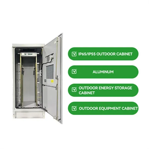
Find Prefabricated Telecom Shelter manufacturers, suppliers, dealers & latest prices from top companies in India. We are the first Indian company to provide 'Ready to Erect' Telecom Shelters in India with in-house Design, Engineering, Manufacturing and Erection / Installation capability all across India for efficient and cost effective operations of telecom equipment. (Dust Weather proof Insulated Cabin for. Prominent & Leading Manufacturer from Greater Noida, we offer portable prefabricated shelters and puf insulated telecom shelter. Our broad scope of pre-assembled covers incorporates a wide exhibit of Portable Telecom Shelters. Designed for rapid deployment and exceptional durability, our portable shelters are ideal for various applications, including the telecom and railway. Leading Manufacturer of prefabricated telecom shelters from Faridabad. Constructed with durable materials, these shelters ensure reliable performance.
[PDF]
Voltage level: Industrial facilities often use multiple voltage levels (such as 1kV, 10kV, 400V), and it is necessary to ensure that the cable distribution box layout separates different voltage systems to avoid interference. A distribution box is the heart of any electrical system. It takes the incoming power and safely distributes it to different circuits throughout your building. Whether in a home or an industrial facility, this box keeps your electrical setup organized, functional, and efficient. However, the key to. Design requirements for low voltage distribution boxes cover NEC, IEC, and safety standards to ensure reliable, compliant electrical installations. You must make safety your top priority when working with low voltage distribution boxes. Protection requirement: According to the fault risk (such as short. For Branch Circuits (the conductors spanning from the final overcurrent device or breaker to the actual outlet, light fixture, or equipment), NEC Informational Note No. 4 recommends a maximum voltage drop of 3%. This ensures that the device at the end of the line receives at least 97% of the panel. For distribution boxes that handle only lighting circuits or small power loads, if the incoming wire size is less than 10 square millimeters and the number of circuit switches is fewer than 20, the width of the box should be calculated by summing the width of the switches and adding an additional.
[PDF]

There is no internal separation within the switchgear. All components, including busbars, circuit breakers, and terminals, are installed within a single compartment. Though it is cost effective and compact, suitable for low risk installations, but it provides limited safety and. Forms of internal separation define how a low-voltage switchgear and controlgear assembly is divided into internal compartments by means of barriers or partitions. Terminals not separated from the busbars Terminals separated from the busbars (separation of the busbars from the functional units + separation of the functional units from each other) Terminals not separated from the busbars Terminals separated from the busbars ( (separation of the busbars from. Segregation levels in LV boards are categorized into four main forms, as specified by IEC standards: This basic form has no separation between functional units, busbars, or terminals. It is the simplest and least costly design but offers minimal safety and maintenance advantages. In practice, what this implies is that busbars, control units, and cable terminations all occupy the same space in the switchboard enclosure. The only separation is the external metal or. In low voltage switchgear, an internal separation form refers to the physical separation between bus bars, functional units, and terminals. These separations are achieved using barriers or partitions.
[PDF]

This section provides an overview for busbars as well as their applications and principles. Here are the top-ranked busbar companies as of May, 2026: 1. Chatsworth. Busbars also known as bus bars, barra electrica, or busbar electrical systems are essential components in modern electrical distribution. Whether used in industrial bus bars, EV charging, renewable energy plants, or building infrastructure, busbars offer compact, efficient, and safe current. High Voltage Busbars are critical components in electrical power systems, designed to conduct high voltage electrical currents efficiently and safely. They are used in substations, switchgear assemblies, and electrical distribution systems to connect different parts of the system and manage the. According to Mordor Intelligence, the busbar market was valued at USD 5. 3 billion in 2023 and is projected to reach USD 7. 5% during the forecast period. What. The global busbar market will expand at a great rate and reach USD 19. 24% between 2023 and 2033. The top companies in busbar market are Siemens AG, Connectivity, Mersen, Schneider Electric, Rogers Corporation, Legrand.
[PDF]

Cable tray/protective casings are to be assigned with a safe Working Load. The test should be performed according to IEC 60068-2-75:2014 pendulum hammer. (Refer the sketch shown below) The test should be carried out on samples of cable tray lengths or cable ladder. Cable tray load testing ensures your trays can hold the weight without bending or breaking. The bearing capacity is the most basic testing item for the quality of the cable tray. The load-bearing test is also called the SWL (safe working load) test, which is to test the bearing capacity of the cable tray according to the standards of the International Electrotechnical Association. The. Meka Pro measures the safe workload of the cable management systems and corresponding deflection in accordance with the IEC 61537 standard. The safe workload (SWL) is a load [kg/m] that creates a deflection of 1/100 in the span, or if a 1/100 deflection is not achieved, it is the force that creates. This international standard outlines the requirements and tests for cable tray systems used for electrical installations. Whether you're a manufacturer, contractor, or quality assurance engineer, understanding the testing behind IEC 61537 can help ensure your systems meet global safety benchmarks. Samples of ladder should consist of two side-members with one rung positioned centrally. Sa es of the plastics can be maintained for the intended purpose and the installation location. In this particular.
[PDF]

In a news conference today at the University of Chicago, the U. Department of Energy unveiled a report that lays out a blueprint strategy for the development of a national quantum internet, bringing the United States to the forefront of the global quantum race and ushering in a. In a news conference today at the University of Chicago, the U. Exploration and reserves, storage, imports and exports, production, prices, sales. Sales, revenue and prices, power plants, fuel use, stocks, generation, trade, demand & emissions. In the next 20 years, almost three billion people will join the middle class, propelling global demand for more and better housing, televisions, cars, food, water, energy, and myriad other goods and services. But, with increasing strain on the planet's resources, meeting this demand could carry. Husain is director of the FREEDM Systems Center With funding from the National Science Foundation (NSF) leveraged by additional industry support, the Engineering Research Center has sparked the growth of dozens of clean energy businesses in Raleigh's Research Triangle, making the region an. In a news conference today at the University of Chicago, the U. Below are quick statistical highlights providing an overview of the industry. For more detailed information, please see EEI's other resources. 2024 National Energy Resource Mix Coal.
[PDF]

Testing solar panels is easy with a multimeter! To test the current, simply connect the multimeter to the panel's output. Set it to read DC current. To test voltage, set your multimeter to. A $15 multimeter and 5 minutes of testing can diagnose most solar panel problems. Measure Voc (open circuit voltage) — if it reads 0V, the panel or wiring is dead. If it reads 60–80 % of rated, a bypass diode has failed. If Voc is normal but the system is not producing, the problem is downstream. Solar panels are usually tested under standard conditions using a light source that mimics the light from the sun on a clear day. You can use the following method if you want to test your solar panel under standard conditions. We will cover the. A multimeter is a tool that measures the voltage, current, and resistance of an electrical circuit. Fluke recommends using the Fluke 117 Electrician's Multimeter or Fluke 283 FC CAT III 1500 V Digital Multimeter to test solar modules. This helps you spot issues early and keep your system running efficiently. By the end of this guide, you will be equipped with the knowledge to diagnose.
[PDF]

When it comes to testing fiber optic cables, a Visual Fault Locator (VFL) is an essential tool in your toolkit. A VFL is used to detect faults, breaks, or bends in fiber optic cables by emitting a bright red light that is visible even through the fiber's jacket. Let's dive into everything you need to know about mastering VFLs. It's a cost-effective and. Visual Fault Locator (VFL) testing is one of the most fundamental inspection methods used in FTTH, ODN, and data center environments. A VFL emits a visible red laser (typically 650 nm) that travels along the fiber core and leaks out at points of excessive loss, fiber breaks, or microbends. Although. The Fiber Visual Fault Locator Kit is an essential tool for network technicians and engineers; it provides an accurate and quick method of finding such problems as breaks, bends or faults that may affect the network's operation. It works by injecting a visible red laser light (usually in the 650nm wavelength) into the fiber. When the light encounters a fault, such as a break, bend, or bad splice, it leaks out of the fiber, making the. Conducting efficient, repeatable fiber optic cable certification requires an array of specialized test equipment: Optical Loss Test Set (OLTS) – Integrates adjustable light source and power meter for efficient, Tier-1 insertion loss testing. Visual Fault Locators – Handheld devices projecting.
[PDF]

